Today's post is contributed by Richard Gain (richgain on Thingiverse), designer of the nicely-constructed puzzles from Day 324 and Day 332 as well as the beautiful and terrible Szilassi polyhedron from Day 325. He has designed a stunning array of challenging burr puzzles that he makes using the program Burr Tools; check out his Shapeways shop and Thingiverse collection. Over the next two posts he's going to walk us through how to use Burr Tools to design printable puzzles!
I have been 3D printing puzzles since 2008, first with the help of Shapeways and, since 2011, on home-made types of RepRap 3D printer.
I quickly discovered that puzzles could be categorised in a new way depending on whether the shapes had overhanging parts which need the support option to be turned on in the slicing software.
I decided to call these "printable" and "non-printable," harking back to the old wood-workers' classification of burr puzzles as either "notchable" or "non-notchable" depending on whether they could be made only with a saw. (Almost any puzzle can be printed on a home 3D printer by turning on automatic support but this usually leaves messy surfaces when it is removed, which can stop the puzzle from working well.)
There is a fantastic collection of freely available puzzle designs at Puzzle Will Be Played with many new ones being added every week. This site can provide many wonderful new puzzle ideas for 3D printing, but please respect the designer's copyright and keep these for personal use only. Commercial reproduction can usually be arranged by negotiation with the designers.
Choosing a printable puzzle is simply a matter of looking at a new design and working out whether there are any overhanging sections or not. Sometimes a piece can be rotated into a new position which has no overhangs but many pieces are complex and awkward shapes which would need support material however you positioned them. My own Lock Ness Cube is an example of such a puzzle.
VASP by Terry Smart is a brand new design of a classic burr puzzle. It would have been trickier to make out of wood because it is "non-notchable" (look at the internal corners of pieces D, I and J) however it is "printable" because there are no pieces with overhanging parts.
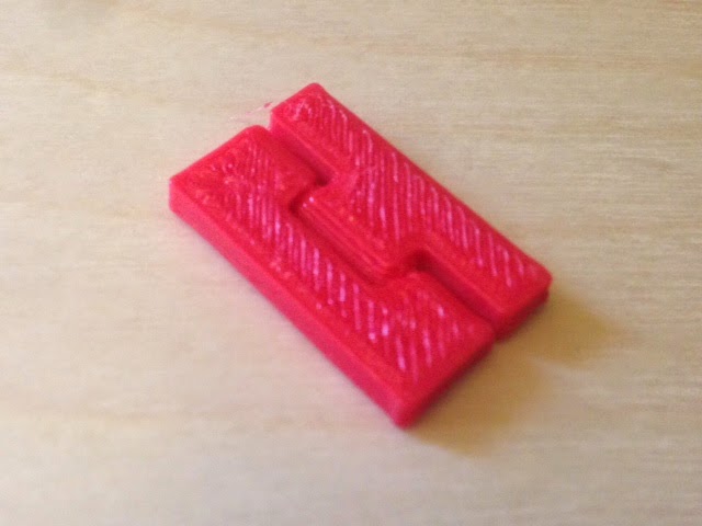
Let's start with something a little easier though. Looks Easy by Bram Cohen is also brand new and looks like an interesting puzzle challenge which should be easy to print, if not to solve!
By far the easiest way to make new 3D printable puzzle designs is to use a free program called Burr Tools. Download it now from http://burrtools.sourceforge.net/ - the Download section is at the bottom of the page. The latest version is 0.6.3 but it is always worth checking for new updates.
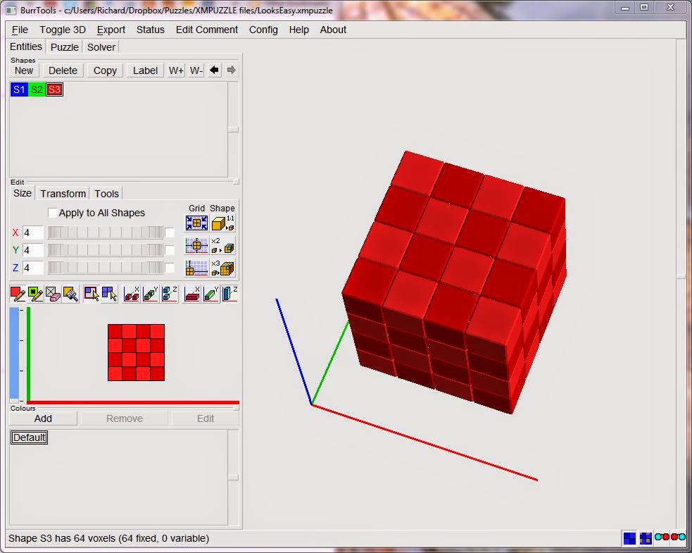
Once you have installed it to your preferred location, start the program up and you should see a screen like this:
Select File - New - Brick - OK. (Brick is the default type)
On the Entities tab, click New shape. A blue S1 will appear.
Now we can set the size of the pieces in blocks. This is a 4x4x4 cube puzzle so let's set X, Y and Z to 4 by dragging the wheels horizontally.
Now click in the small 4x4 grid to paint the shape of the first layer of piece A. You can zoom and rotate the 3D view in the large window.
To paint on the second layer you would need to drag the slider on the left up a notch. We won't need that for this puzzle.
Go back to the top and click New shape again. A green S2 will appear.
Draw the shape of piece E in the 4x4 grid.
Now would be a good time to save your work.
We only need to create the different shapes - copies can be added later - but there is one more shape we need; the target shape of the finished puzzle, in this case a 4x4x4 cube.
Click New shape again to get red S3.
We could simply paint every cell on all four layers but there is a quicker way. Just above the 4x4 grid there is a row of icons. Click the 5th icon to change to Rectangular Selection mode, and also the last icon to toggle "Draw in all Z layers." Now carefully click and drag in the 4x4 grid from top left to bottom right and you should have a large red cube.
Do experiment with these toggle switches when you are ready to learn more about the program. It is also worth checking out the Transform and Tools tabs which hide some very useful functions, like automatically making the internal cubes variable (may or may not be present) when there are internal holes in the puzzle. 'Looks Easy' has 0 internal holes so we don't need that now.
For the final step in this section, let's finish entering the puzzle design. Go to the top and change from Entities to Puzzle.
Click New. Click the red S3 shape, then click the Set Result button.
Click the blue S1 shape, then click +1 four times.
Click the green S2 shape, then click +1 four times.
Now select the Solver tab and click Start to get Burr Tools to show you the solution for this puzzle. Ticking the Disassemble check-box will show you how to solve the puzzle step-by-step by dragging the Move slider.
Note that if the solution involves rotating any of the pieces then Burr Tools will be able to show the final positions but not the disassembly steps.
In part 2 we'll look at how to turn this puzzle into a 3D printable design...
Welcome to MakerHome
We've completed our yearlong print-a-day project!
All new material is now at Hacktastic: www.mathgrrl.com
Saturday, August 9, 2014
Friday, August 8, 2014
Day 347 - Friday Fail: Self-Intersecting Faces Edition
It seems that the MakerBot Desktop software has an upper bound on the number of "self-intersecting faces" that can be in a model. When I had just a couple of squares hinged together, I didn't have any problems. But with six square faces all with hinges and snaps, there were over 500 of these bad faces (according to MeshLab), caused by triangles that end up somehow sharing parts in the OpenSCAD code. Desktop can't open a file with that much badness, and for a long time I went through a crash/restart/crash/turn-it-off-and-on-again/restart/crash/uninstall/reinstall/forever cycle until I finally figured out that I should maybe go repair the mesh of my file. When I got the number of self-intersecting faces down under 50 by adding additional "fudges" to my OpenSCAD code, MakerBot Desktop could finally open it.
Here's what the remaining 41 self-intersecting faces look like in MeshLab, after selecting Cleaning and Repairing and applying Select Self Intersecting Faces. I could get rid of these also but at this point thing were working so I left well enough alone.
With fudge set to a teeny 0.1, we can sneak in fudges all over the OpenSCAD code with no effect on the printed size of the model, like this:
translate([0-fudge,2*i*snapwidth,0-fudge])
cube([height/2+gap+fudge,snapwidth-space+fudge,height+fudge]);
The trick is to make sure that none of your fudges intersect exactly with any of your other fudges. To avoid having two triangles that share the same face you need to keep track of how you've nudged everything - or change the value of fudge - so that you don't fudge-nudge other things into the same place.
Thursday, August 7, 2014
Day 346 - Personalizable Crazy Cube
One really cool thing about a fold-out cube is that you can print things on the faces without using supports and then fold up the cube to get an object with interesting protrusions all over. To print a closed cube with crazy sides would be really unreliable, but to print a flat one is easy. Here's one crazily decorated hinge/snap cube net:
And here is it folded up:
The Customizable Hinge/Snap Cube Net was made in OpenSCAD and then imported into Tinkercad, where we added all the crazy shapes. Here's a public Tinkercad design you can modify to make your own Crazy Cube:
Tinkercad link: https://www.tinkercad.com/things/gu7kcfQV5C3-personalizable-crazy-cube
Thingiverse link: http://www.thingiverse.com/thing:436982
Settings: Printed on a Replicator 2 with .3mm/standard settings, raft but no supports.
Wednesday, August 6, 2014
Day 345 - Customizable hinge/snap Cube net
This week we're attempting to combine three of our previous designs into one:
Thingiverse link: http://www.thingiverse.com/thing:436839
Settings: Printed on a MakerBot Replicator 2 at .3mm layer height with standard settings, raft, and no supports. Use the Thingiverse Customizer to set the sizes and clearances however you like.
- Print-in-Place Fidget Cube (for the hinges)
- Poly-Snaps: Tiles for Building Polyhedra (for the polygon code and homogeneous snaps)
- Polyhedra - Hinged Nets (to update to OpenSCAD/Customizer)
So far we've managed to get snaps and hinges into the one right-angled model and get everything to fit. Today's code can make corners with two hinges and a snap, or two snaps and one hinge! In other words, we can now make nets for cubes:
Settings: Printed on a MakerBot Replicator 2 at .3mm layer height with standard settings, raft, and no supports. Use the Thingiverse Customizer to set the sizes and clearances however you like.
Tuesday, August 5, 2014
Day 344 - Personalizable Hinged Initials
Here's one use for yesterday's hinge - some stand-up hinged initials for young C:
Of course, if your initials aren't CGR then this model doesn't help you very much. So here's a design you can customize yourself in Tinkercad:
Tinkercad link: https://www.tinkercad.com/things/7CItNykrXZQ-personalizable-hinged-initials
Thingiverse link: http://www.thingiverse.com/thing:436888
Technical notes, Tinkercad/educator flavor: If you are supervising students who are personalizing this design in Tinkercad, I highly recommend having your students use the Ruler tool. To do this, select the Ruler from the "Helpers" section of the right-hand menu column in Tinkercad, and put the Ruler down anywhere on the Workplane (preferably somewhere out-of-the-way, maybe in a far corner). When the Ruler is on the Workplane, any object you select will have dimensions that you can modify by typing into the number fields. To personalize this object, first Ungroup it and remove the CGR initials. Put down letters from the right-hand Tinkercad column and resize them to fit in the boxes. Then use Adjust/Align and the arrow keys to get everything lined up just right.
Monday, August 4, 2014
Day 343 - Customizable Cone Hinge
Today we made a cone hinge module that can be used inside other projects:
Thingiverse link: http://www.thingiverse.com/thing:436737
Settings: Optimized for a MakerBot Replicator 2 with default .3mm/low settings, with raft but (and this is key) no supports. For different printers, to change scale, or for tighter/looser hinges, try changing the clearances in the Customizer at the Thingiverse link.
Technical notes, OpenSCAD flavor: This is a conical hinge, so never needs support material. The picture below shows a cross-section about halfway through.
The space between the protruding cones and the cone-shaped holes is controlled by a parameter called clearance, and the space between the hinge and the adjacent bars is controlled by the parameter called gap. A non-customizable parameter called fudge allows us to push things imperceptibly one way or another so as to avoid having identical duplicate triangles in our output mesh. Here is the full OpenSCAD code for this object:
// mathgrrl cone hinge
//////////////////////////////////////////////////////
// parameters
// Length of the complete hinge
length = 20;
// Height (diameter) of the hinge
height = 3;
// Clearance between cones and holes
clearance = .7;
// Clearance between hinge and sides
gap = .6;
// Parameters that the user does not get to specify
$fn=24*1;
border = 2*1;
fudge = .01*1; // to preserve mesh integrity
corner = 0*1; // space between hinge and corner
hinge_radius = height/2;
cone_height = 1.5*hinge_radius;
//////////////////////////////////////////////////////
// renders
rotate(90,[0,1,0])
translate([-hinge_radius,0,0])
hinge();
translate([0,hinge_radius+gap,0]) bar();
translate([0,-2*border-hinge_radius-gap,0]) bar();
//////////////////////////////////////////////////////
// module for hinge
module hinge(){
rad = hinge_radius;
clr = clearance;
len = (length-2*corner)/3;
con = cone_height;
// left outside hinge = (cylinder+box)-cone
difference(){
union(){
translate([0,0,corner]) cylinder(h=len-clr,r=rad);
translate([-rad,0,corner]) cube([2*rad,rad+gap,len-clr]);
}
translate([0,0,corner+len-con-clr+fudge]) cylinder(h=con,r1=0,r2=rad);
}
// inside hinge = cylinder+box+cone+cone
union(){
translate([0,0,corner+len]) cylinder(h=len,r=rad);
translate([-rad,-rad-gap,corner+len]) cube([2*rad,rad+gap,len]);
translate([0,0,corner+len-con]) cylinder(h=con,r1=0,r2=rad);
translate([0,0,corner+2*len]) cylinder(h=con,r1=rad,r2=0);
}
// right outside hinge = (cylinder+box)-cone
difference(){
union(){
translate([0,0,corner+2*len+clr]) cylinder(h=len-clr,r=rad);
translate([-rad,0,corner+2*len+clr]) cube([2*rad,rad+gap,len-clr]);
}
translate([0,0,corner+2*len+clr-fudge]) cylinder(h=con,r1=rad,r2=0);
}
}
//////////////////////////////////////////////////////
// module for bar shape
module bar(){
cube([length,2*border,height]);
}
Sunday, August 3, 2014
Day 342 - Hinge
In preparation for a new hinge-related project, today we redesigned our conical hinge maker.
Technical notes, clearance flavor: We made this hinge in OpenSCAD and tomorrow we'll have a customizable version up on Thingiverse, with modifiable tolerance parameters. Clearance dimensions matter a lot! Here's a picture of the six practice and failed designs that led up to the seventh working design:
Saturday, August 2, 2014
Day 341 - Ganesha statue
Today we printed another scanned object from the Art Institute of Chicago, a Ganesha statue on MyMinFactory made by coskucan. According to the model description and trusty Wikipedia, Ganesha is known as a remover of obstacles and a god of beginnings, both of which particularly appeal to me these days. And the model prints beautifully:
MyMiniFactory link: http://www.myminifactory.com/object/ganesha-at-art-institute-chicago-1834
Settings: Printed at 300% scale with .2mm layer height on a Replicator 2 in about 3.5 hours.
MyMiniFactory link: http://www.myminifactory.com/object/ganesha-at-art-institute-chicago-1834
Settings: Printed at 300% scale with .2mm layer height on a Replicator 2 in about 3.5 hours.
Friday, August 1, 2014
Day 340 - Buddha statue
Today we printed tomburtonwood's very descriptively-titled Buddha Seated in Meditation (Dhyanamudra), Chola period, c. 12th century, Art Institute of Chicago. Power-designer Tom Burtonwood (@tburtonwood on Twitter) is the Artist-in-Residence at the Art Institute of Chicago and he has been doing some really interesting work with scans, modular animal parts, 3D-printed books, and giant multicolor 3D prints. He also has an excellent Beginners guide to 3D printing site. Here's his Buddha scan:
Thingiverse link: http://www.thingiverse.com/make:90405
Settings: Printed on a MakerBot Replicator 2 on .3mm layer height in just over 20 minutes.
Thingiverse link: http://www.thingiverse.com/make:90405
Settings: Printed on a MakerBot Replicator 2 on .3mm layer height in just over 20 minutes.
Thursday, July 31, 2014
Day 339 - Minecraft Ringtail spider
Today we printed toddsplod67's Minecraft spider from Thingiverse, for two reasons. First, Minecraft. Second, this 3D model is part of a tutorial for the 3D-modelling software Ringtail. There are so, so, so many modeling programs that we want to learn and it was nice to see a walkthrough tutorial for this one.
Thingiverse link: http://www.thingiverse.com/make:90401
Settings: MakerBot Desktop .3mm/low on a Mini.
Technical notes, future flavor: Once this print-a-day-for-a-year blog is done (end of August!) we're going to transition into a series of posts about getting started with various 3D-modeling programs... which means that we'll have to learn how to get started with more 3D-modeling programs...
Wednesday, July 30, 2014
Day 338 - Tinkercad Math Gyros
Today we gave a 3D-printing workshop at MoMath Summer Camp. Everyone got to make and print their own math gyro in Tinkercad. Here's what the students made:
Tinkercad link: https://www.tinkercad.com/things/1RUJSJvRboQ-math-gyro-maker
Thingiverse link: http://www.thingiverse.com/thing:431348
Settings: Printed on a MakerBot Replicator 2 and a MakerBot Replicator Mini at .3mm layer height.
Technical notes, Tinkercad flavor: We got the idea for this project from Josh Ajima (@DesignMakeTeach on Twitter), master of 3D-printing education. His Personalize a Gimbal project starts with an existing gimbal design from Thingiverse and allows students to customize and personalize it in Tinkercad. He also designed an excellent MOM Gimbal which everyone should print for their geeky moms. (I'm looking at you, C. Where is my MOM Gimbal?) Riffing on this idea we designed a new gimbal/gyro in Tinkercad and then chose some shapes from the Community Shape Generators that have modifyable parts (number of petals/sides, etc). Students learn how to move, align, and group objects and then use that knowledge to put together a customized gyro from pre-made pieces:
Specifically, the student should choose one small inside hole and use the sliders in the Shape Script to change the number of sides/petals or the amount of twist in the shape. Then Align the small hole with the small blue gyro center and Group them together. For the outside, the student should choose a large shape and customize it to their liking, then Align and Group the large shape with the large hole. Finally, select the customized outer ring together with the orange, yellow, green, and customized blue gyro rings, and Align and Group together to make the final gyro. Here's what the designs looked like after four groups of students made three gyros a piece (some groups made more than one design):
Technical notes, educator flavor: What makes this project work is that the resulting prints are very likely to print successfully. Beginning designers do not typically make reliable prints at first, which can be frustrating if you are under time constraints or giving a one-time workshop instead of a multi-session class. If a student accidentally resizes the gyro pieces then the object won't spin and/or print correctly, so if you want to make absolutely sure the prints will work then you should check the gyro ring measurements on each design. It's easy to replace the insides with a copy of the working gyro rings while still preserving the customizations that the student made. Halfway through printing we did a filament color swap. Having two colors is particularly effective on spinning gyros. If you have sturdy thumbs then you can also break the gyros apart and mix-and-match them back together again.
Tuesday, July 29, 2014
Day 337 - Calvin 3D scan!
We recently got a scan of Calvin's head at the 3D Photo Booth in the MakerBot Retail Store on Mulberry Street in NYC. About 18 months ago we got a scan at the same location (see this JMU MakerLab post), and the technology at the 3D Photo Booth has changed significantly for the better. This scan is a full 360 degrees around, and even the curly mop of hair looks great:
Thingiverse link: http://www.thingiverse.com/thing:397337
Settings: Printed on a MakerBot Replicator 2 at .3mm/low with raft and supports.
Thingiverse link: http://www.thingiverse.com/thing:397337
Settings: Printed on a MakerBot Replicator 2 at .3mm/low with raft and supports.
Monday, July 28, 2014
Day 336 - Pile of Pikachu
Here's why you work so hard (see yesterday's post) to get a reliable print at 50% size: Because you need a lot of them! Young C has been spending a lot of time playing Pokemon at the Brooklyn Strategist (one of the best places on earth!) and will be bringing these to the next tournament:
Thingiverse link: http://www.thingiverse.com/make:89385
Settings: Printed four at a time on an Afinia H-Series with .3mm layer height.
Thingiverse link: http://www.thingiverse.com/make:89385
Settings: Printed four at a time on an Afinia H-Series with .3mm layer height.
Sunday, July 27, 2014
Day 335 - Low-Poly Pikachu
Today's print is FLOWALISTIK's nicely stylized Low-Poly Pikachu model from Thingiverse. The design of this model is great, and just like the ones we printed on Day 282, FLOWALISTIC made very nice choices for the few polygons in the model. We wanted a very small model so we printed it at half size. It's adorable. Pika pi!
Thingiverse link: http://www.thingiverse.com/thing:426352
Settings: This model was printed with our loaner Afinia H-Series printer at 50% scale, in beautiful ABS yellow!
Technical notes, remeshing flavor: Because everything I do is a total hack, it took me the better part of an afternoon to strengthen this tail. Here is a before-and-after shot with the original FLOWALISTIK model on the left and my strong-tail hack on the right:
I tried to take the easy way out and add a block or wedge to the tail using Tinkercad, but I couldn't seem to do that without it looking weird, so I decided to go the infinitely more complicated MeshLab/TopMod route. In MeshLab it turned out that all the normals were inside-out (not that that had anything to do with the tail problem):
So I flipped them with "Invert Faces Orientation" under the "Normals, Curvature, and Orientation" menu:
Then I exported the model as an OBJ so that I could load it into TopMod. Using the "Connect Edges Mode" I selected face-edge pairs to connect in a symmetric way around the tail. In the picture below, the three triangles you see at the join of the tail are what I added to the model:
That sounded really easy when I just typed that but it took me a long time to figure out how to make that work in TopMod, and along the way I tried a lot of other things that failed miserably. In fact, even this was a sort of failure, because adding those three triangles caused some nasty non-manifold problems. I exported from TopMod and imported back into MeshLab so I could run "Remove Faces from Non-Manifold Edges" and a bunch of other stuff from the "Cleaning and Repairing" menu (see Day 148, for example). Even after that, something was still crazy and the model wouldn't slice right, so I went to my last resort strategy and imported the model to Tinkercad, in the hopes that re-exporting the model would magically fix the problem. AND IT DID, thank goodness.
Those of you with actual skills out there, please don't laugh at my stumbling through the dark. Sometimes I think the whole point of this blog is to show that you can muddle through most things even if you have no idea what you're doing, as long as you keep plugging along. Follow me, I have no idea what I'm doing! On the other hand, if you know what you are doing then feel free to leave a comment so I can be smarter about this next time...
Saturday, July 26, 2014
Day 334: Snap!
We printed ZortraX's Zortrax Buckle from Thingiverse for the sole purpose of hearing that satisfying *snap* that these types of buckles make. Can the snap be 3D-printed? Yes it can! This buckle works perfectly and makes a lovely snap. The buckle then unsnaps very nicely and seems to be holding up very well under repeated use. This is a great design!
Thingiverse link: http://www.thingiverse.com/make:89372
Settings: We printed this on a Replicator 2 with .15mm layer height, since that most closely matched the instructions for the model. To get .15mm layer height we printed on .1mm/High setting and then bumped up the layer height to .15mm.
Thingiverse link: http://www.thingiverse.com/make:89372
Settings: We printed this on a Replicator 2 with .15mm layer height, since that most closely matched the instructions for the model. To get .15mm layer height we printed on .1mm/High setting and then bumped up the layer height to .15mm.
Friday, July 25, 2014
Day 333 - Friday Fail: Eighteen pieces edition
Today we printed ATDT8675309's Cube Puzzle on Thingiverse, which consists of eighteen rods that assemble into a nice regular structure. Except that we failed at the assembly part! Maybe we're all thumbs, had too much coffee, aren't as clever as we thought we were, etc...
Thingiverse link: http://www.thingiverse.com/make:89371
Settings: Printed on a MakerBot Replicator Mini at Standard settings with raft, and layer height bumped up to .3mm.
UPDATE: ATDT8675309 has put up a video walkthrough of the solution to this puzzle. Thank you, that was very helpful! My difficulty was with keeping the pieces together on the first few steps; if you can get past that then the pieces fit together in a very regular way with of course the one different piece being able to slide in at the end. Here's a hint for keeping everything aligned at the beginning: put two of the pieces underneath the sides to keep the cross-pieces at the correct height until the puzzle starts being rigid. The puzzle fits together just right with perfect clearance, and stays together nicely after being assembled. Here's the assembled model:
Thursday, July 24, 2014
Day 332 - Six piece box
A few days ago we printed richgain's Printable Interlocking Puzzle #1, and today our print is his Printable Interlocking Puzzle #2. For me this was actually a pretty difficult puzzle to put together. However the pieces fit together very well with good clearances; nothing needs to be forced. The model looks nice even when all the pieces are printed in the same color, because with translucent filament the pieces have different looks and finishes from different viewpoints. This is a very clean model, and nice enough to give as a gift.
Thingiverse link: http://www.thingiverse.com/make:89369
Settings: We printed these on a Replicator 2 with .2mm layer height, as recommended in the instructions for the model.
Thingiverse link: http://www.thingiverse.com/make:89369
Settings: We printed these on a Replicator 2 with .2mm layer height, as recommended in the instructions for the model.
Wednesday, July 23, 2014
Day 331 - POP Customizable Function Bracelet
Trading sine and cosine turns yesterday's POW bracelet into this POP:
Thingiverse link: http://www.thingiverse.com/thing:426255
Settings: MakerBot Replicator 2 on .3mm/low.
Technical notes, math flavor: Yesterday's POW bracelet was based on this function:
If we put the "2" weight on the cosine instead of the sine then we get the function for today's bracelet:
If you look at the POW and the POP bracelets together you can kind of see how each one is sort of "inside-out" from the other. Of course the function we wrapped around the circle to make the POP bracelet needed a modified shift, amplitude, and frequency:
Finally, here it is wrapped around the circle as a parametric function:
Thingiverse link: http://www.thingiverse.com/thing:426255
Settings: MakerBot Replicator 2 on .3mm/low.
Technical notes, math flavor: Yesterday's POW bracelet was based on this function:
Finally, here it is wrapped around the circle as a parametric function:
Tuesday, July 22, 2014
Day 330 - POW Customizable Function Bracelet
Today we kick the math up a notch and use a combination of two trigonometric functions to define a bracelet curve. POW!
Thingiverse link: http://www.thingiverse.com/thing:426034
Settings: MakerBot Replicator 2 with .3mm/low resolution and raft.
Technical notes, math flavor: The main thing that characterized each of our previous bracelet designs was a change of frequency. The TRI bracelet (Day 320) used a trigonometric function with a very low frequency of 3:
The SUN bracelet (Day 328) allowed a variable frequency:
The RIB bracelet (Day 329) used a very high frequency of 72:
This time we're going to not only change the frequency, but also fundamentally change the function by incorporating a cosine as well:
Notice that the frequencies for the sine and cosine functions are different; this is what gives our bracelet its interesting shape.
Technical notes, OpenSCAD flavor: Below is the full code for the POW bracelet. We've separated the code for the wave function and the wrapping of the wave function, and used the more complicated trigonometric function described above.
// mathgrrl function bracelet - POW design
/////////////////////////////////////////////////////////
// resolution parameters
$fn = 24*1;
step = .25*1; // smaller means finer
// Thickness, in mm
th = .4;
/////////////////////////////////////////////////////////
// size parameters
// Diameter of the bracelet, in mm
diameter = 60;
radius = diameter/2;
// Height of the bracelet, in mm
height = 10;
/////////////////////////////////////////////////////////
// style parameters
// Amplitude of the wave, in mm
amplitude = 6;
// Frequency of the wave
frequency = 12;
/////////////////////////////////////////////////////////
// define the wave function
function f(t) = 1+sin(2*frequency*t)*cos(frequency*t);
/////////////////////////////////////////////////////////
// define the wrapped wave function
function g(t) =
[ (radius+amplitude*f(t))*cos(t),
(radius+amplitude*f(t))*sin(t),
0
];
/////////////////////////////////////////////////////////
// renders
// the bracelet
linear_extrude(height=height,slices=height/.4)
function_trace(rad=th, step=step, end=360);
/////////////////////////////////////////////////////////
// module for tracing out a function
module function_trace(rad, step, end) {
for (t=[0: step: end+step]) {
hull() {
translate(g(t)) circle(rad);
translate(g(t+step)) circle(rad);
}
}
};
Settings: MakerBot Replicator 2 with .3mm/low resolution and raft.
Technical notes, math flavor: The main thing that characterized each of our previous bracelet designs was a change of frequency. The TRI bracelet (Day 320) used a trigonometric function with a very low frequency of 3:
1+sin(3t).
The SUN bracelet (Day 328) allowed a variable frequency:
1+sin(frequency*t).
The RIB bracelet (Day 329) used a very high frequency of 72:
1+sin(72*t).
This time we're going to not only change the frequency, but also fundamentally change the function by incorporating a cosine as well:
1+sin(2*frequency*t)*cos(frequency*t).
Notice that the frequencies for the sine and cosine functions are different; this is what gives our bracelet its interesting shape.
Technical notes, OpenSCAD flavor: Below is the full code for the POW bracelet. We've separated the code for the wave function and the wrapping of the wave function, and used the more complicated trigonometric function described above.
// mathgrrl function bracelet - POW design
/////////////////////////////////////////////////////////
// resolution parameters
$fn = 24*1;
step = .25*1; // smaller means finer
// Thickness, in mm
th = .4;
/////////////////////////////////////////////////////////
// size parameters
// Diameter of the bracelet, in mm
diameter = 60;
radius = diameter/2;
// Height of the bracelet, in mm
height = 10;
/////////////////////////////////////////////////////////
// style parameters
// Amplitude of the wave, in mm
amplitude = 6;
// Frequency of the wave
frequency = 12;
/////////////////////////////////////////////////////////
// define the wave function
function f(t) = 1+sin(2*frequency*t)*cos(frequency*t);
/////////////////////////////////////////////////////////
// define the wrapped wave function
function g(t) =
[ (radius+amplitude*f(t))*cos(t),
(radius+amplitude*f(t))*sin(t),
0
];
/////////////////////////////////////////////////////////
// renders
// the bracelet
linear_extrude(height=height,slices=height/.4)
function_trace(rad=th, step=step, end=360);
/////////////////////////////////////////////////////////
// module for tracing out a function
module function_trace(rad, step, end) {
for (t=[0: step: end+step]) {
hull() {
translate(g(t)) circle(rad);
translate(g(t+step)) circle(rad);
}
}
};
Monday, July 21, 2014
Day 329 - RIB Customizable Function Bracelet
This time we've fixed the frequency at 72, the amplitude at 2mm, and left the diameter, height, and slant variable to make a RIB bracelet. This bracelet is not stretchy but it is very fluid and bends/flattens easily, making it more comfortable to wear than the TRI (Day 322) or the SUN (Day 328).
Thingiverse link: http://www.thingiverse.com/thing:425784
Settings: MakerBot Replicator Mini using Standard settings and raft, with layer height bumped up to .3mm.
Technical notes, slant flavor: In this design you choose an integer slant from -3 to 3 that represents the number of ridges that the twist extrude moves through. Doing this is easy by setting the twist extrude degrees to the value slant*360/frequency. Since the frequency (number of ridges) for this design is fixed at 72, each ridge takes up 5 degrees. Therefore a slant of 3 translates to a twist extrude to the left 3*5=15 degrees, and a slant of -3 makes a twist to the right 15 degrees.
Sunday, July 20, 2014
Day 328 - SUN Customizable Function Bracelet
Continuing the bracelet series from Day 320 and Day 322, today we printed a new customizable sun-shaped variation. The bracelet is a little bit stretchy but not as much as emmett's classic Stretchlet design.
Thingiverse link: http://www.thingiverse.com/thing:425503
Settings: Printed on a Replicator 2 and a Replicator Mini at .3mm layer height, with raft. Note that no fancy settings are needed because the design is already just an outline of a bracelet.
Technical notes, design upgrade flavor: In a comment to Day 322, kitwallace mentioned a much nicer redesign using ruled surfaces which he described on his blog The Wallace Line. I've got a couple more completed bracelet designs to post and then I'm going to switch to kitwallace's method. Very cool!
Technical notes, math flavor: This bracelet differs from the TRI design on Day 320 in that the trigonometric function has a variable frequency instead of a fixed frequency of 3. Specifically, we are wrapping the function
around the circle to make these bracelets. The twistiness of the transluscent blue and opaque white bracelets in the picture come from a twist during the OpenSCAD extrude process, not from the mathematical function. However when we upgrade to code based on kitwallace's suggestion above, we will be able to encode the twist - as well as many other transformations - mathematically.
Thingiverse link: http://www.thingiverse.com/thing:425503
Settings: Printed on a Replicator 2 and a Replicator Mini at .3mm layer height, with raft. Note that no fancy settings are needed because the design is already just an outline of a bracelet.
Technical notes, design upgrade flavor: In a comment to Day 322, kitwallace mentioned a much nicer redesign using ruled surfaces which he described on his blog The Wallace Line. I've got a couple more completed bracelet designs to post and then I'm going to switch to kitwallace's method. Very cool!
Technical notes, math flavor: This bracelet differs from the TRI design on Day 320 in that the trigonometric function has a variable frequency instead of a fixed frequency of 3. Specifically, we are wrapping the function
radius+amplitude*(1+sin(frequency*t)))
around the circle to make these bracelets. The twistiness of the transluscent blue and opaque white bracelets in the picture come from a twist during the OpenSCAD extrude process, not from the mathematical function. However when we upgrade to code based on kitwallace's suggestion above, we will be able to encode the twist - as well as many other transformations - mathematically.
Saturday, July 19, 2014
Day 327 - Saturday guest: AuntDaisy and the Electra
Today's post is contributed by Austin Day, aka AuntDaisy on Thingiverse, from Aunt Daisy Scientific Ltd., UK. AuntDaisy is the designer of the Trilobite articulatum model that we printed on Day 130 as well as the beautiful 3D-printable modular origami Electra model that we printed on Day 323. Thank you Austin/AuntDaisy for guest posting today!
Why 3D print an origami model?
Like most families, we love to decorate our Christmas tree and have spent many happy hours making origami stars, angels and woven Danish Hearts. My favourite star has to be David Mitchell’s beautiful Electra - it’s an incredibly symmetrical model, and, unlike some modular origami models, is surprisingly robust. But, when you have children, you soon find that things get squashed or shot at with Nerf bullets :-) While straightening out Electra for the umpteenth time, I thought – why not 3D print this?
Modular Origami
Most people think of origami models as being folded from a single sheet of paper (for example, Robert J Lang’s creations), but modular origami joins lots of small, folded modules together to make a larger model that is often mathematical in style. Kunihiko Kasahara’s Origami Omnibus and David Mitchell’s Mathematical Origami are good introductions to Maths & origami. If you want to be more adventurous, then I recommend David Mitchell’s Paper Crystals, now in its second edition - “Electra” has appeared in both.
Electra - what is an Icosidodecahedron?
Electra is a skeletal polyhedral model based on the 60 edges of an icosidodecahedron – a mixture of a dodecahedron (with 12 pentagonal faces) and an icosahedron (20 triangular faces). When assembled, rings of modules dance around each other – five membered rings (pentagons) alternate with three (triangles), but never meet - except at discrete corners (and, even then, under supervision). There are also rings of ten modules forming great circles (like the equator) that run around the whole polyhedron. As you turn Electra in your hands, mirror, 2-fold, 3-fold, 5-fold and even partial 10-fold symmetry magically appears – it’s not surprising that some quasicrystals, with their forbidden 5-fold symmetry, have atoms positioned around an icosidodecahedron.
How was the 3D model designed?
I started with the X-shaped paper modules and soon found that the top point was a right angle, the tops of the tabs & pockets were at 45 degrees to the base, and the angle between the arms of the X was roughly 60 degrees. Also, ten of the modules made a ring, so the angle between the tilted ends of the pockets (for the tabs) must be 36 degrees (=360/10).
The next step was to draw it on paper and calculate the angles & lengths properly. This is where my (spherical) geometry came unstuck! Why wasn’t the X angle exactly 60 degrees? It looked to be 60 degrees, three of the modules met to make a triangle - it must be 60 degrees… It wasn’t - that little tilt between the modules made the maths “messy”.
I started trying to calculate the angle on paper, then moved to OpenSCAD, but soon gave up – it was great for designing in, but couldn’t tell me when the modules touched. Brute force and Solidworks was the approach that worked – tweaking the X angle until a ring of 5 modules and another ring of 3 modules fitted together properly. And the “60” degree angle was really 63.434957… [Or arccos(1/sqrt(5)) = arctan(2), which is 180 degrees minus the angle between the faces of a dodecahedron. Silly me for not knowing!]
The final step was to put little catches on the tabs so they locked in to a pocket on the opposite side of the module. These proved to be tricky to print, very fragile, and left horrible lumps and bumps on the outside of the module. So I experimented with smooth tabs – they worked much better. A bit more tweaking of the overall module thickness, the tab thickness (40% of this) and the pocket width (1/3) and we’re ready to print and assemble a whole model.
Assembly & colour schemes
There are lots of ways of colouring Electra – David Mitchell recommends chaotic / random colouring or 5 contrasting colours. If you go for 5 colours, then the 6 modules of a particular colour form the corners of an octahedron – a beautiful, hidden symmetry that might have tickled Dürer or Escher, it certainly surprised me.
For the assembly, there’s a simple rule – make a ring of 5 modules, then add modules to make rings of three around them, then 5-rings around the 3’s and so on... For the 5 colour version, you also have to make sure that the colour on the corner of a 5-ring matches that on the opposite corner of a 3-ring.
Once the first model was made, I experimented with changing the outside of the modules – over on Thingiverse there’s a spherical version, amongst others. Or we can be more colorful, changing the filament colour after, say, 25%, 50% & 75% of printing; for example, here are some three-color modules:
And the resulting 3-color Stripey Electra!
Conclusions
To sum up – origami and 3D printing do mix. Both can produce beautiful mathematical models - but Murphy’s law rules and it sometimes takes perseverance and practice. Oh, and a tame mathematician is always useful. :)
Thanks to David Mitchell, Electra now comes in two flavours – the 30 module vanilla shown here; and twice as much fun “Electra 60” - based around a rhombicosidodecahedron with triangles, squares and pentagons. This is where paper beats plastic – paper will happily cope with changes in the module angles… but I can’t!
Acknowledgments
A big thank-you to Laura Taalman for her fascinating blog and inspirational models – and for inviting me to be a guest blogger. Also to David Mitchell for his beautiful models and origami books.
References
David Mitchell’s “Electra” http://freespace.virgin.net/dave.mitchell/galleriesmodulardesigns.htm
David Mitchell, "Paper Crystals”, 2nd edition, http://www.amazon.co.uk/dp/0953477495 or www.amazon.com/dp/0953477495
David Mitchell, “Mathematical Origami: Geometrical Shapes by Paper Folding”, www.amazon.com/dp/189961818X
Kunihiko Kasahara’s “Origami Omnibus”, www.amazon.com/dp/4817090014
My 3D printed version of Electra, http://www.thingiverse.com/thing:127857
The British Origami society, http://www.britishorigami.info/
Origami USA, https://origamiusa.org/
Friday, July 18, 2014
Day 326 - Friday Fail: Gyro edition
Guess what, I started a Gyro project.
As usual I'm starting with a big pile of fails. My goal is to make a reliable gyro model in Tinkercad to use in introductory 3D-printing workshops. I'd much rather use OpenSCAD so I could parametrize the tolerances, but I want something that a beginner could pick apart and modify/remix by adding fun shapes in Tinkercad. (Shout-out to Josh Ajima, @designmaketeach on Twitter, for this great idea!) Looking for the Goldilocks rings - not fused together, not falling apart; just right. Stay tuned...
Subscribe to:
Comments (Atom)