Or the Professor and Mary Ann, as they prefer to be called. Our last two Catalan solids are the Triakis Tetrahedron (dual of the Truncated Tetrahedron and Kleetope of the tetrahedron) and the Tetrakis Hexahedron (dual of the Truncated Octahedron and Kleetope of the cube/hexahedron). And now that I have them here side-by-side, I finally get what "triakis" and "tetrakis" mean: the former means that triangular pyramids were added to obtain the object, and the latter means that square pyramids were used.
Thingiverse link: http://www.thingiverse.com/thing:282534
Settings: Same as the last week of Catalan prints. Stay tuned tomorrow for a round-up of the slicing, sizing, and mesh choices that built this set of thirteen wireframe polyhedra.
Welcome to MakerHome
We've completed our yearlong print-a-day project!
All new material is now at Hacktastic: www.mathgrrl.com
Tuesday, March 25, 2014
Monday, March 24, 2014
Day 210 - Rhombic Dodecahedron
We're almost at the end of the Catalan series! Today we printed our eleventh, the Rhombic Dodecahedron, dual of the Cuboctahedron (which we also constructed with printed snap-tiles on Day 87).
Thingiverse link: http://www.thingiverse.com/thing:282499
Settings: MakerWare .3mm/low with custom reduced-support slicing profile, on a Replicator 2.
Technical notes, tessellation flavor: The Rhombic Dodecahedron has a very interesting property: it fills space. What I mean by that is that you can stack them up to pack together perfectly, with no open spaces between. This is a pretty rare property: the only Platonic solid that fills space is the cube; the only Archimedean solid that fills space is the Truncated Octahedron; and the only Catalan solid that fills space is the Rhombic Dodecahedron.
For more information see "Simplicity is not Simple: Tesselations and Modular Architecture", the cover article for Math Horizons about Gregg Fleishman's space-filling housing units that I wrote with Eugenie Hunsicker of Loughborough University in 2002. Twelve years later I can now finally stack up a handful of Rhombic Dodecahedra and see for myself!
Sunday, March 23, 2014
Day 209 - Afinia Menger
Most of our prints for this blog are made on a MakerBot Replicator 2, since that's what we usually have at the house. But the other day one of the Afinia H-Series printers from the JMU 3-SPACE Classroom made a guest visit, on its way to the Expanding Your Horizons Conference, where Rebecca Field gave a wonderful 3D-printing demonstration and math talk to a large group of middle-school girls. While the Afinia was here, Rebecca printed a demo Menger cube using owens' Customizable Menger Sponge model from Thingiverse. It worked wonderfully!
Settings: Afinia 3D .3mm default fast, with a raft and with custom stand included in the model but no supports.
Thingiverse link: http://www.thingiverse.com/make:71022
Settings: Afinia 3D .3mm default fast, with a raft and with custom stand included in the model but no supports.
Thingiverse link: http://www.thingiverse.com/make:71022
Saturday, March 22, 2014
Day 208 - 26mm Level 3's and the Sketch A Menger Cross-Section Competition™
I love to root for the underdog: David vs Goliath, Buffy vs the entire Hellmouth, the Baudelaire twins against Count Olaf and his evil theatre troupe. Today the role of the underdog will be played by the affordable consumer-level MakerBot Replicator 2 ($2,200), going head-to-head with the wickedly expensive Dimension Elite ($24,000 + $3K/year service contract) at the JMU Engineering Department. Of course, since Stratysys acquired MakerBot last year, this is a friendly fight indeed. :)
Battle time! We used owens' Customizable Menger Sponge design on Thingiverse to print a 26mm Level 3 Menger cube, pictured on the left below. John Wild in Engineering was kind enough to use the Dimension Elite to print a 26mm Level 3 Menger cube for us last summer, pictured on the right. The Dimension Elite prints with a dissolvable support material, so they didn't have much trouble removing the supports from this tiny model. Our model on the left didn't need any supports at all since it was printed on its corner(!), so the holes are actually clearer on our Replicator 2 model. It looks great!

Settings: A 26-mm Level 3 model prints up in just under 90 minutes with no raft or support with MakerWare .2mm/standard on a MakerBot Replicator 2. You can even get a decent print using the .3mm/low resolution! The model prints on its corner, supported by a very clever custom stand designed by owens on Thingiverse.
Thingiverse link: http://www.thingiverse.com/make:71021
We love these so much, we are printing them whenever we have the chance. If we make enough of them we could stick them together build a Level 4!
Three of these six small Menger cubes will be prizes in the the Sketch A Menger Cross-Section Competition™ that was held at this week's G4G11 Conference in Atlanta over Twitter, by Matt Parker from the mathS department at Queen Mary, University of London. (Be sure to also check out Matt Parker's online shop mathsgear.co.uk and website standupmaths.com.)
Matt is @standupmaths on Twitter, and he asked his army of followers to try their luck at sketching Menger cube slices. There were an amazing number of very good submissions, with things I never could have drawn by hand without looking at the actual model! We chose three winners and I've added a runner-up:
Jose Barrera (@JBarreraGT) took first place with three really amazing sketches:
Dawn R (@Boneist on Twitter) took 2nd place with this unique choice of slice:
Sadie Robertson (@Saddle098 on Twitter) took some time off from working out circuits to win Honorable Mention:
And Alex Hunsley (@quaplek on Twitter) had a late entry with some of the most beautiful paper I have ever seen:
Thank you Matt Parker and everyone who submitted entries to the slice-drawing competition! Perhaps we can have more competitions in the future...
Friday, March 21, 2014
Thursday, March 20, 2014
Day 206 - Menger coverups
At this year's Gathering for Gardner Conference (G4G11) I gave a short talk about 3D printing sliced Menger sponges. So that people could look at the sliced models and guess what the sliced face looks like, I made some white printed coverups to hide the sliced faces.
Thingiverse link: slice-covers added to the model set at http://www.thingiverse.com/thing:250557
Settings: MakerWare .3mm/low. The cover shapes can be held onto the Menger slices with poster tack, although this does sometimes leave a small amount of blue residue on the model afterwards.
Congratulations to Glen, Tanya, and Daniel for winning the Menger-slice-drawing contest at the conference; each got a 43mm Level 3 Menger sponge (see Day 161) as a prize!
Wednesday, March 19, 2014
Day 205 - Disdyakis Triacontahedron
Today is our largest Catalan print so far, with a diameter of over 120 millimeters - about the size of a very large grapefruit. One cool thing about this model is if you look only at the large 10-degree vertices you see the points of an icosahedron, while if you look at the pentagons surrounding those vertices you see the faces of a dodecahedron. In addition, you can see the rhombuses (rhombi?) of its Kleetope, the Rhombic Triacontahedron, and find 4-, 6-, and 10-degree vertices corresponding the the 4-, 6-, and 10-sided faces of its dual, the Truncated Icosidodecahedron.
Thingiverse link: http://www.thingiverse.com/thing:281174
Settings: MakerWare custom profile described in Day 194, on a Replicator 2, with sizing using the method from Day 195.
Technical notes, support flavor: Near the beginning of this series of Catalan solids, I worried that I'd be spending too much time on one type of model, and that things would get boring. But kind of the opposite has happened, I think: because we are printing the same sorts of things every day, we can take time in these posts to describe more of the math, design, and technical things that go into the prints. For example, we've barely talked about support - except of course to mention that we're using the support profile we made for knots and Catalan solids, described on Day 194. But how much support is that? How much cleanup is required for these models? Because this model is very large and has particularly small, thin, triangular openings, it is a good worst-case scenario to explore. So we took some pictures along the way this time...
As you can see in the picture below, we chose to print the model on one of its large, high-degree vertices. We previewed the slicing in this orientation and in the "flat on one face" orientation, and this one took less support, plastic, and time. I think it is because the edges coming up from the large vertex are at a significant angle, while the edges that extend around a triangle face are much more horizontal and therefore would need more support. In the picture you can see that support towers are being built to hold up the top edges of the model, but that the lower edges themselves do not need much support.
In the next picture we see the finished model, with thin support towers up to the top:
From the front we see the thin curtains of support towers that are hiding under the edges:
Removing the support is not that difficult, because the support is very thin and also not that securely attached to the model. It took me just under five minutes to remove the support from this large model, by snipping to break the support and then pulling it out from the holes. The cleaned-up model weighed in at 45 grams, and the pile of support weighed only 37 grams.
Tuesday, March 18, 2014
Day 204 - Pentakis Dodecahedron
Yes, we seem to have fallen behind again. We can talk more about that on some "Friday." For now we'll catch up with the rest of our Catalan prints and some additional Menger prints before getting on to new designs.
Before we start, I want to give a shout-out to three people on Thingiverse that have been doing excellent work with polyhedra:
Thingiverse link: http://www.thingiverse.com/thing:281166
Settings: MakerWare custom profile described in Day 194, on a Replicator 2, with sizing using the method from Day 195.
Before we start, I want to give a shout-out to three people on Thingiverse that have been doing excellent work with polyhedra:
- pmoews, who has over 160 designs on Thingiverse that include beautiful designs of every type of polyhedron or geometric figure that you could imagine.
- pdragy, whose recently Thingiverse-Featured extensive design collection Customizable Convex Polyhedra was the inspiration for the wireframe models that I have been making.
- kitwallace, who has written some beautiful OpenSCAD code for Generated Polyhedra that works very quickly even for very large models, and who will soon be contributing a guest post to this blog to talk about those designs.
Thingiverse link: http://www.thingiverse.com/thing:281166
Settings: MakerWare custom profile described in Day 194, on a Replicator 2, with sizing using the method from Day 195.
Monday, March 17, 2014
Day 203 - Rhombic Triacontahedron
This Catalan solid is the Rhombic Triacontahedron, the dual of the Icosidodecahedron (which we've already printed twice before as a snap-together model, in Day 89 and Day 117).
Thingiverse link: http://www.thingiverse.com/thing:274427
Settings: .3mm/low on an Afinia H-Series, with the support density reduced to 2 layers in order to make the supports easier to remove.
Technical notes, build platform flavor: This was my first print using Afinia's Borosilicate Glass build plate and BuildTak Platform Surface. Both worked wonderfully, with the glass seeming to get much hotter all the way to the edges than the usual Afinia perf board, and the BuildTak providing the necessary adhesion (although it itself is not sticky, just rougher than the glass). I do need to find some larger binder clips, however, because mine are a bit too small to hold this new setup in place. I'll do a "print to the edge" test on the glass+BuildTak combination later this spring.
Technical notes, filament flavor: This model looks snowy white because of the great matte colors you can get with ABS, especially the Afinia Premium. Most of the PLA filament I've used is a bit too shiny for my taste, with the exception of MakerBot's wonderful translucent PLA filament colors. If you're looking for a matte PLA then the best I can recommend is MakerBot's "Warm Gray", although they are currently out of stock for the Replicator 2. However, you can order it for the 5th-gen Replicators and it will be the same filament, just on a thinner and taller spool that looks somewhat like a film reel. You can't use the 5th-gen spools on the Replicator 2 but you can rewind the filament onto an old-style MakerBot spool or use a separate filament stand.
UPDATE: The Rhombic Triacontahedron wireframe is the shape made by Roger vonOech's StarBall puzzle, which I just bought from Robert Fathauer's lovely shop at G4G11.
Sunday, March 16, 2014
Day 202 - Triakis Octahedron
New fact of the day: If you add a pyramid to each face of an octahedron, then you are taking its "Kleetope." A cool new word for me, leading to the next Catalan solid in our list: the Triakis Octahedron.
Thingiverse link: http://www.thingiverse.com/thing:274367
Settings: MakerWare custom profile described in Day 194, on a Replicator 2. Sizing was determined using the method from Day 195; at the end of the Catalan series we'll do a recap, including the sizing parameters for each polyhedron and how they were obtained.
Technical notes, design flavor: The Catalan wireframes I've been printing are a bit stylized, with vertices that become larger according to their degree. This is because of the remeshing that I am choosing in TopMod, specifically the "Doo Sabin" remeshing. I went with this because I like that I can easily differentiate between different types of vertices; for example, in today's model the vertices that belong to the underlying octahedron (before the "kleetoping") are larger and stand out, while the vertices that form the topes of the added pyramids are smaller. In addition the extra bit around each corner helps make a very stable model that can be dropped on the floor, thrown, and otherwise abused without breaking.
Technical notes, Kleetope flavor: We printed a Kleetope earlier, on Day 199; the Triakis Icosahedron was the Kleetope of the icosahedron. In fact, each of the Platonic solids gives rise to a Kleetope that is a Catlan solid with isosceles-triangular faces:
- the Triakis Tetrahedron is the Kleetope of the tetrahedron;
- the Triakis Octahedron is the Kleetope of the octahedron;
- the Tetrakis Hexahedron is the Kleetope of the cube (a.k.a. the hexahedron);
- the Pentakis Dodecahedron is the Kleetope of the dodecahedron; and
- the Triakis Icosahedron is the Kleetope of the icosahedron.
Technical notes, capitalization flavor: I have decided that Catalan solids are cool and deserve to be capitalized, but I can't bring myself to capitalize my old friends the Platonic solids. Somehow they look silly all dressed up like that. Sorry, capitalization police.
Saturday, March 15, 2014
Day 201 - Saturday guest: owens and the Tetrahemihexahedron
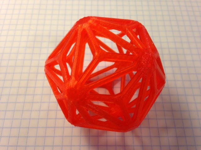
Today's post is contributed by Bill Owens, also known as owens on Thingiverse. He is the creator of the Customizable Menger Sponge and Customizable Sierpinski Tetrix models that cleverly print without support due to the help of some custom stands that print with the models. Thank you, owens, for being our first guest blogger!
I just published a model of a Tetrahemihexahedron on Thingiverse. It is a cool-looking but fairly simple polyhedron, with just six vertices that it shares with the octahedron, but it's a nice object to be able to model and hold in your hands in order to really understand its shape. And it has an interesting property that makes it more challenging to model than most polyhedra.
Thingiverse link: http://www.thingiverse.com/thing:269732
Settings: Cura with .3 mm layers, 10% infill, 0.8 mm shells (two layers), 0.6 mm top/bottom (also two layers) and cooling fan at full, on our OB1.4 with 1.75 mm PLA and a heated glass bed. No supports or raft are needed, but with a non-heated bed I'd recommend a brim if printing on the hollow side.
Technical notes, math flavor: The key thing to know about the Tetrahemihexahedron is that it only has seven sides, despite how it looks in the picture above. Four sides are equilateral triangles, and the other three are squares; you can see one of them if you look straight at any of the vertices. Each square goes through the center of the object, and all three of them cross each other but those crossings don't constitute edges; the squares are still squares, not cut into triangles. This makes the Tetrahemihexahedron an object that can't really exist in 3-space, in some ways analogous to the Klein surface (aka the Klein bottle) whose neck has to pass through its side in order to connect back to itself.
Technical notes, OpenSCAD flavor: Despite the impossibility of this object existing in 3-space, it is possible to make a model of it, by accepting that the squares actually will intersect and we'll just have to pretend that they don't. So to create it I started with the vertices of an octahedron, generated by referencing the square pyramids from Day 184. I laid out the four equilateral triangles and the three squares, and asked OpenSCAD to render the model. It told me that some of my faces weren't laid out correctly; in order to render the model with the correct appearance, it needs to have the vertices of each face in clockwise order when viewed from the outside. That's not an uncommon mistake for me, and I jumped right to the always-handy View:Thrown Together mode; if you have any bad faces, it will color them pink so you know what to fix. Unfortunately, what I discovered is that each of the squares was both good and bad. Taking the square in the XY plane as an example, when viewed from above (+Z) the vertices were clockwise and the face was fine. But that same square was also visible from below (-Z) and from that perspective it was backwards, with counterclockwise vertices.
There was clearly no way to fix this problem, so I decided to cheat a little and break up each square into four right triangles. I methodically redid the vertices, making sure that each one was clockwise from the outside, and finally OpenSCAD would render the object. Then I tried to export it to STL, and received a much more serious error: it was not a manifold object.
For OpenSCAD, being manifold means that the object has no holes (it would hold water), and that the object has at most two faces connected along an edge. Because of the way I broke up the triangles, my object had four faces along each of the edges that met in the center. Obviously that had to change.
The first step to fixing this problem was a realization that if I wasn't trying to make a perfect model I didn't really have to use all of the vertices. In fact, I only had to model one quarter of the object, and duplicate that small tetrahedron with the appropriate rotation.
module onetetra() {
polyhedron(
points = [
[0.5,0.5,0], // 0
[-0.5,0.5,0], // 1
[0,0,1/sqrt(2)], // 2 (top vertex)
[0,0,0], // 3 (center)
],
triangles = [
[0,2,1],
[0,1,3],
[0,3,2],
[1,2,3],
]);
}
module tetrahemihexahedron() {
union() {
onetetra();
rotate(180,[0,0,1]) onetetra();
rotate(180,[1,1,0]) onetetra();
rotate(180,[-1,1,0]) onetetra();
}
But once again, I'd produced a non-manifold object. The simplest way around that was to add fillets, in this case tiny rectangles that would run along the intersection and break it up, so each visible face connected only to the fillet, and nothing connected at the actual intersection.
Making a long, skinny cube to be a fillet was also easy, but that created one more problem. In order to completely eliminate the bad intersection the fillet had to extend all the way out to each vertex, but that meant the corners of the fillet would hang over and extend past the edge of the model.
Appearance-wise this wasn't great, but it would also cause problems for printing because the tiny corners of the fillet would effectively lift the model off the printbed, and make the first layer consist of just three tiny points.
To solve that, I first tried trimming the fillet cube with a much larger cube turned on its corner, but of course that wasn't exactly right. Then I tried a cone, to make the fillet look as though it had been sharpened like a pencil, but it still stuck out. Finally I realized that the right answer was a simple octahedron, the one whose vertices I'd started with; once I used that to remove the corners of the fillet, it lined up perfectly.
The finished model looks pretty good even in the OpenSCAD rendering, with the fillets just barely apparent. Because of the limitations of 3D printers, they completely vanish from the final print. I encourage you to print your own, and to get a better feel for this curious little polyhedron.
UPDATE: Owens has now published new models of the Stewart B4,3 and B4,4 polyhedra to Thingiverse that have the same type of impossible square-face intersections as this Tetrahemihexahedron.
Friday, March 14, 2014
Day 200 - Friday Fail, candlestick edition with bonus rant
Every week there is more failure.
Tinkercad link: https://www.tinkercad.com/things/fPH71QxCeSw-day-200-cgr-candlestick-lathe
Thingiverse link: http://www.thingiverse.com/make:69779
Settings: MakerWare .3mm/low on a Replicator 2.
Technical notes: I'm no artist, so to get the profile of C's face as the side of this vase required some tracing. Specifically, I sized a .jpg of C's profile to be the same as the drawing window in anoved's Customizer, and then put a piece of paper over the screen to trace the outline of his face from the .jpg. Then I put the paper over the box in the Customizer and looked through it to guide the mouse and trace out the profile. A *lot* of failure was involved here, and I had to try the Customizer sketch many times before it looked right. Then my initial try at printing a vase failed because of some massive overhang under the chin part of the profile. Trying to resketch to avoid that overhang didn't work; somehow every orientation came with some unacceptable overhang. In the end I sketched a thinner model, downloaded the solid .stl model output from anoved's Customizer, and imported it into Tinkercad, where I made a hole for a 7/8" candle and made a septagon indentation at the top. The candlesticks were printed in white and then colored in later with a silver Sharpie. They look pretty good but it's weird to pick them up because although they look a bit metallic, they each weigh only 32 grams!
But those who seek only to avoid failure will never succeed at anything new. If you want to succeed every time at making something, go down to the Build-a-Bear shop in the mall, buy a Paint-by-Numbers kit, or cook a microwave TV dinner. Expect things to be done for you and that everything will just work without you having to do anything interesting. And then go read Seth Stevenson's article I tried a 3D printer and all I got was plastic goo in Slate.
It is difficult for me to express strongly enough how disappointed I was in Stevenson's article while still remaining nice. When you buy a tennis racket or a chessboard, are you surprised when you aren't automatically a great tennis player or clever at chess? Does buying a new stove make you a good cook? Of course not, and using a 3D printer is no easy ride, either.
The reason this article upsets me isn't because it is negative about 3D printing. There are plenty of negative things to talk about regarding 3D printing: copying keys, printing guns, copyright violations, non-standard filament spool sizes, and yes, the fact that sometimes the learning curve is steep. And sure, 3D printing isn't yet at the point where every household needs or wants to have a 3D printer. What upsets me is that Stevenson's dismissive, snarky article perpetuates the feeling that we should all expect things to be handed to us, fully functional. That we shouldn't have to think, or learn, or be creative, or fail.
The best spin I can think of for this article is that Stevenson set out to write an article about 3D printing, ran up against a deadline, and decided that if he couldn't succeed before his print deadline then the best thing to do would be to complain that 3D printers are just so impossible to deal with that no normal human could possibly find them useful. That's the best spin, because the alternative would mean that he genuinely was not willing to fail or learn after falling down just a few times, and that possibility is very sad. It would mean that he approached 3D printing as if it were just another way to consume - instead of trying to make any models himself, he only tried printing what he dismissed as "trinkets and geegaws" and then was disappointed when they didn't pop out of his 3D printer like it was a vending machine. If you want a quick and cheap source of little plastic trinkets, then go to the Dollar Store. If you want to actually learn to make something yourself then go get a 3D printer.
In the Thingiverse community we may start out designing "geegaws" but we are learning the skills to make bigger and better things all the time, and to teach those that come after us. The filament-extrusion 3D printing technology that we hobbyists have on our desks is decades old, and isn't representative of what the pros can do with 3D printing (bioprinting, circuitry, airplane parts, houses, you name it). But limited as it is, we don't want to mindlessly consume our entire existence from the shelves of Target. We want to MAKE things.
Being driven to make rather than just accept the status quo is what enabled projects like RoboHand's Mechanical prosthetic hands printed on a MakerBot Replicator 2 and Manu Prakesh's 50-cent paper microscope that folds like origami, both of which replace expensive and inaccessible consumer products with things that are inexpensive and easy to share. 3D printing enables doctors to do complicated facial reconstructions, builders to make new types of houses, and even helps NASA create tools for space exploration.
I'll never make anything as important as those things, but at least when I failed at printing this Friday, I had enough grit to get up and try again until it worked. In the end my failed orange chalice turned into a pair of silver candlesticks, using anoved's Customizable Chalice Lathe on Thingiverse and a profile image of my son's face and mop of curly hair:
Thingiverse link: http://www.thingiverse.com/make:69779
Settings: MakerWare .3mm/low on a Replicator 2.
Technical notes: I'm no artist, so to get the profile of C's face as the side of this vase required some tracing. Specifically, I sized a .jpg of C's profile to be the same as the drawing window in anoved's Customizer, and then put a piece of paper over the screen to trace the outline of his face from the .jpg. Then I put the paper over the box in the Customizer and looked through it to guide the mouse and trace out the profile. A *lot* of failure was involved here, and I had to try the Customizer sketch many times before it looked right. Then my initial try at printing a vase failed because of some massive overhang under the chin part of the profile. Trying to resketch to avoid that overhang didn't work; somehow every orientation came with some unacceptable overhang. In the end I sketched a thinner model, downloaded the solid .stl model output from anoved's Customizer, and imported it into Tinkercad, where I made a hole for a 7/8" candle and made a septagon indentation at the top. The candlesticks were printed in white and then colored in later with a silver Sharpie. They look pretty good but it's weird to pick them up because although they look a bit metallic, they each weigh only 32 grams!
Thursday, March 13, 2014
Day 199 - Triakis Icosahedron
For the last week I've been printing whatever polyhedra appeal to me, and today I realized that everything I've printed is a Catalan solid. Today is the fifth, the Triakis Icosahedron - dual of the Truncated Dodecahedron, and the first one so far that has triangular faces. This way leads madness; I'm going to have to print all of them now. Luckily, there are only thirteen Catalan solids. (Of course later I could print all of the Archimedean solids, then the Johnson solids, then Platonic solids and prisms and anti-prisms and arrgggh...)
Thingiverse link: http://www.thingiverse.com/thing:273353
Settings: MakerWare custom profile described in Day 194, on a Replicator 2.
Thingiverse link: http://www.thingiverse.com/thing:273353
Settings: MakerWare custom profile described in Day 194, on a Replicator 2.
Wednesday, March 12, 2014
Day 198 - Deltoidal Icositetrahedron
Another day, another Catalan solid. Today it is the Deltoidal Icositetrahedron, dual of the Archimedian solid known as the Rhombicuboctahedron. As we discussed yesterday, the fact that these are duals means the following two things:
Thingiverse link: http://www.thingiverse.com/thing:273327
Settings: MakerWare custom profile described in Day 194, on a Replicator 2.
- Since every vertex of the Rhombicuboctahedron is degree four, every face of the Deltoidal Icosahedron has four sides.
- Since every face of the Rhombicuboctahedron is either a triangle or a square, every vertex of the Deltoidal Icositetrahedron has degree three or four.
The Deltoidal Icositetrahedron looks like the little brother of the Deltoidal Hexecontahedron from Day 196:
Thingiverse link: http://www.thingiverse.com/thing:273327
Settings: MakerWare custom profile described in Day 194, on a Replicator 2.
Tuesday, March 11, 2014
Day 197 - Pentagonal Icositetrahedron
Today's print is yet another Catalan solid, the Pentagonal Icositetrahedron - dual of the Snub Cube which we printed with Poly-Snaps in Day 116, and giraffe-cousin of the Pentagonal Hexecontahedron we printed on Day 194. Designed using Mathematica, MeshLab, and TopMod as described in Day 194, with scaling factor determined as described in Day 195.
Thingiverse link: http://www.thingiverse.com/thing:272848
Settings: Same as the past few days, detailed in Day 194, on a Replicator 2.
Monday, March 10, 2014
Day 196 - Deltoidal Hexecontahedron
Continuing our string of Catalan solids, today we printed a Deltoidal Hexecontahedron.
Thingiverse link: http://www.thingiverse.com/thing:272833
Settings: MakerWare custom profile described in Day 194, on a Replicator 2.
Technical notes, math flavor: Catalan solids are the polyhedra that are the duals of the Archimedean solids. To recap with some nice pictures from Wikipedia, the three Catalan solids we've printed (on the left) have the following Archimedean duals (on the right):
Sunday, March 9, 2014
Day 195 - Disdyakis Dodecahedron
The Disdyakis Dodecahedron is a convex Catalan solid with a lot of cool properties, including:
- It's the dual of an Archimedian solid, the Truncated Rhombicuboctahedon;
- It has 26 vertices, 72 edges, and 48 faces, and 26 - 72 + 48 = 2;
- It is a lot of fun to say out loud: Disdyakis Dodecahedron!
But the main reason we printed this particular polyhedron today is because it looks cool, kind of like the frame of an Octahedron with fancy asterisks added to its faces:
Thingiverse link: http://www.thingiverse.com/thing:270367
Settings: MakerWare custom profile described in Day 194, on a Replicator 2.
Technical notes: Here's the fun part. (Warning: When a mathematician says that, it means that they are about to spend a long time talking your ear off about something.) The yellow model above isn't the first Disdyakis Dodecahedron we printed. When we followed the modeling procedure used to create yesterday's Pentagonal Hexecontahedron, we got the much smaller red model shown in the front of this photo:
Clearly, next to the open, delicate Pentagonal Hexecontahedron shown in blue, the red Disdyakis Dodecahedron is too small and dense; we need to scale up the model. There are two things to consider here: First of all, we have to scale the model before we create the wireframe, or else the edge thickness will increase as the model gets larger - and we want the edges to look the same in all of our polyhedron models. Second of all, although we could try to eyeball a satisfying scale for the new polyhedron, it would be much better to have some kind of consistent scaling factor that we could apply to all of our polyhedron models. And that's a math problem!
Let's walk through the problem. We want to print a set of polyhedra that look like a matching set, even though they will have many different types of faces and vertex degrees. All the initial scaling rules we thought of had problems. For example, we could insist that every model has the same smallest edge length. Not a bad idea, and might make things look pretty consistent, right? Well, it happens that this is exactly what Mathematica does, and since we used Mathematica to get the original polyhedral form for our models, the blue and red polyhedra already have this property! If you look at the picture you can see that the edge length on the red model is actually the same as the shortest edge length on the blue model. Here's another possible rule: Make all triangles the same sizes in all models, and make all pentagons the same proportionally larger size, and so on. Once again, this is already the case for the red and blue models, but the red one is somehow far more dense. One more: what if we let the area of the smallest face be the constant? Well, then models that involve pentagons and hexagons are going to look a lot different than models that involve triangles and hexagons. Nothing is working and we are starting to feel more than a little dense for not seeing the answer. Welcome to mathematics!
Wait... DENSE. Density is the key. And what is causing the density here is the amount of the surface area of the polyhedra that is used by the wireframe. Although our model has some extra material at the vertices, the wireframe is essentially made up of the edges of the polyhedron. So what we want to look at is the ratio of the area taken up by the edges to the surface area of the polyhedron. Since all of the edges have the same width, let's focus on their lengths. We can ask Mathematica to find the edge lengths that occur in the Disdyakis Dodecahedron with this command:
N[PolyhedronData["DisdyakisDodecahedron", "EdgeLengths"]]
Output: {1., 1.33771, 1.6306}
Since we can see from the model that these three edge lengths each occur once on every face, the average edge length is:
length = (1 + 1.33771 + 1.6306)/3
Output: 1.32277
We also need to know how many edges are in the model:
edges = PolyhedronData["DisdyakisDodecahedron", "EdgeCount"]
Output: 72
As well as the surface area of the model:
surface = N[PolyhedronData["DisdyakisDodecahedron", "SurfaceArea"]]
Output: 32.0667
From these pieces we'll construct our scaling factor. We'll take the product of length and edges to represent the amount of the polyhedron covered in wireframe (up to some constant multiple based on the width of the edges; let's ignore that for now), and look at the ratio of that product with the surface area. One last thing, though: Since we are going to use this scaling factor to linearly scale the model in each direction, and the ratio we are computing has to do with surface area, we should take the square root of the ratio to get the scaling factor:
scalefactor = Sqrt[(length*edges/surface)]
Output: 1.72338
Now here's the really cool part. We thought that we'd have to multiply this scaling factor by some constant to account for the width of the edges, until we realized that yesterday's print of the blue Pentagonal Hexecontahedron had exactly the look and density that we wanted. So we calculated the scaling factor for that model and it came out to be... wait for it...
Output: 0.980345
In other words, just about 1. Close enough that we can pretend it is equal to 1. This means that relative to our nice airy Pentagonal Hexecontahedron model, our Disdyakis Dodecahedron model should be scaled up by a linear factor of about 1.72338. To get today's yellow model this is exactly what we did, adding the scaling in the MeshLab file conversion step:
Filters/Normals, Curvature, and Orientation --> Scale --> enter scaling factor
Note number 1: Usually when I say "we" I really mean "I", since that is how math people talk for some reason and I can't shake it. But today "we" is really a plural, as my husband Phil was a great sounding board and suggestion-factory for this scaling problem. Thank you Phil!
Note number 2: I apologize for falling behind on this blog, once again. I knew this post would be a doozy so was procrastinating, and also, life and stuff. The good news is that while I was procrastinating I printed about ten more polyhedra wireframes, so I'll have lots to share with you very soon.
Saturday, March 8, 2014
Day 194 - Pentagonal Hexecontahedron
For the next week or two we will be modeling and printing wireframe models of various exotic polyhedra. On Day 192 we developed a method for doing this using Mathematica, MeshLab, and TopMod, and tested three types of meshes. We like the Goldilocks one in the middle (not too angular and not too round), so today we applied it to a very beautiful polyhedron, the Pentagonal Hexecontahedron. This is now my favorite polyhedron; so irregular and yet so regular at the same time!
Thingiverse link: http://www.thingiverse.com/thing:267920
Settings: We printed this on a Replicator 2 using our minimal-support MakerWare custom profile from Day 110. This profile is based on the Standard PLA profile, with the following modifications:
Thingiverse link: http://www.thingiverse.com/thing:267920
Settings: We printed this on a Replicator 2 using our minimal-support MakerWare custom profile from Day 110. This profile is based on the Standard PLA profile, with the following modifications:
- "roofThickness": 0.5,
- "floorThickness": 0.5,
- "sparseInfillPattern": "linear",
- "infillDensity": 0.2,
- "minSpurLength": 0.4,
- "doSupport": true,
- "doSupportUnderBridges": true,
- "supportDensity": 0.1,
- "supportExtraDistance": 0.8,
- "supportModelSpacing": 0.5,
Technical notes: To create the model for this object we used the same procedure we followed in Day 192, detailed below.
- Use Mathematica to create the polyhedron and export to STL:
PolyhedronData["PentagonalHexecontahedron"]
Export["PentagonalHexecontahedron_math.stl", %] - Use MeshLab to convert to OBJ format.
- Use TopMod to remove edges or vertices that don't belong in the wireframe, and then create the frame and remesh:
Wireframe 0.250
Remeshing/4-Conversion/Linear Vertex Insertion
Remeshing/4-Conversion/Doo Sabin
Export as STL - Use MakerWare to size and orient the model. Specifically, Mathematica creates models in inches, so when this model is imported into MakerWare it will be very small (for example, a 2-inch model would only be 2 millimeters). Since there are 24.5 millimeters in an inch, we need to rescale by a whopping 2450%. This makes a really huge model so I scaled by another 50% before printing. By experimenting with the orientation of the model you can sometimes reduce the print time and amount of supports; in this case I re-oriented so that one of the pentagonal faces was flush with the build platform.
UPDATE: Mike Lawler (@mikeandallie on Twitter) alerted me to an related and even more amazing polyhedron posted on Mr. Honner's blog on the same day as this post: a beautiful wooden model of a Dual Snub Hexpropello Dodecahedron. While you are clicking on links you should also check out Mike's excellent blog mikesmathpage where he explores lots of interesting math with his kids!
Friday, March 7, 2014
Day 193 - Friday Fail, angel hair edition
It's Friday! Also, this:
I was trying to make a smaller version of owens' Sierpinski tetrahedron model from Day 189, but stupidity got in the way. Specifically, I started the print and walked away before checking to make sure everything was okay. I know that I definitely Should Not Do This, but I did it anyway. Even worse, I also did it earlier in the day in the JMU MakerLab and caused a similar angel hair catastrophe that in that case required some serious cleanup and a replacement of the ceramic tape on the Replicator 2. In short, I was an idiot today, and the universe caught me on it twice. Fool me once...
Lessons learned which I either already knew or should have known but did not heed:
- Models don't stick as well on tape as they do on acrylic. (See picture above.)
- Models don't stick as well on glass as they do on glass with tape. (At the JMU MakerLab we have a new glass build platform!)
Thursday, March 6, 2014
Day 192 - Mesh-testing a Gyroelongated Pentagonal Bicupola
Inspired by the many sets of polyhedral models on Thingiverse (for example pmoews' Archimedean Solids, Johnson Polyhedra, and Catalan Solids, and pdragy's Customizable Convex Polyhedra), today we experimented with ways to make wire-frame polyhedra. Our test subject was the gryoelongated pentagonal bicupola, which has regular polygon faces but non-regular behavior at its vertices. This sounds fancy but just means that the vertices can look different; for example, in this model there are some vertices that are surrounded by one pentagon, two squares, and one triangle, where in other places there are vertices that are surrounded by four triangles and a square.
Thingiverse link: http://www.thingiverse.com/thing:267193
Settings: MakerWare with custom settings from Day 110 on a Replicator 2.
Expensiveware warning: On this blog I try to stick to free and commonly available software, but for today's object I am pulling out the big guns and using Mathematica, which is very much not free. Mathematica's freeware baby cousin wolframalpha.com also knows about the gryo-pen-bic-whatsit, but Mathematica has much more data and power, and most importantly, can export models to STL.
Technical notes: It is easy to get a 3D polyhedral model in Mathematica using the built-in PolyhedronData package; for today's polyhedron it's as simple as:
So the problem is this: How to turn a model exported from Mathematica into a wireframe? This afternoon I was thinking about this problem and suddenly remembered that there is a little button in TopMod that looks like this:
Problem solved! Export the polyhedron from Mathematica to STL, convert to OBJ using MeshLab (or your favorite online converter) so we can open the file in TopMod, remove the edges and vertices from the mesh that we don't want included in the wireframe, and then press the magic button. The model pictured on the right is the result of this process. The one pictured in the back had a mesh refinement and then a Doo Sabin remesh (see Day 135), and the one pictured on the left had no refinement but then two Doo Sabin remeshings.
UPDATE: Bill Owens (owens on Thingiverse) points out that you can get Mathematica for free on a Raspberry Pi, so for some of you Mathematica *is* freeware!
Thingiverse link: http://www.thingiverse.com/thing:267193
Settings: MakerWare with custom settings from Day 110 on a Replicator 2.
Expensiveware warning: On this blog I try to stick to free and commonly available software, but for today's object I am pulling out the big guns and using Mathematica, which is very much not free. Mathematica's freeware baby cousin wolframalpha.com also knows about the gryo-pen-bic-whatsit, but Mathematica has much more data and power, and most importantly, can export models to STL.
Technical notes: It is easy to get a 3D polyhedral model in Mathematica using the built-in PolyhedronData package; for today's polyhedron it's as simple as:
PolyhedronData["GyroelongatedPentagonalBicupola"]Mathematica can also output a wireframe, give specific vertex coordinates, calculate the surface area of the polyhedron, and lots of other things, including export to STL. However, Mathematica only reliably exports full models, not wireframes (as far as I can figure). We could use Mathematica's vertex coordinates to explicitly construct a wireframe model in OpenSCAD by combining the methods in Day 174 and Day 188, but that would require keeping track of vertex adjacency information. That might be tolerable for just one polyhedron, but would be way too tedious for constructing a big collection of different polyhedral wireframes.
So the problem is this: How to turn a model exported from Mathematica into a wireframe? This afternoon I was thinking about this problem and suddenly remembered that there is a little button in TopMod that looks like this:
Problem solved! Export the polyhedron from Mathematica to STL, convert to OBJ using MeshLab (or your favorite online converter) so we can open the file in TopMod, remove the edges and vertices from the mesh that we don't want included in the wireframe, and then press the magic button. The model pictured on the right is the result of this process. The one pictured in the back had a mesh refinement and then a Doo Sabin remesh (see Day 135), and the one pictured on the left had no refinement but then two Doo Sabin remeshings.
UPDATE: Bill Owens (owens on Thingiverse) points out that you can get Mathematica for free on a Raspberry Pi, so for some of you Mathematica *is* freeware!
Wednesday, March 5, 2014
Day 191 - Filament bracelet
Today we made something very simple: a small, thin rounded tube for turning a scrap of filament into a simple bracelet. Despite how simple this is, it took over a dozen prints to get it just right so that it would hold the filament securely. The resulting bracelet is the top one in the following picture:
Tinkercad link: https://tinkercad.com/things/1u7wu02ELWJ-day-191-filament-bracelet-clasp
Thingiverse link: http://www.thingiverse.com/thing:264544
Settings: MakerWare .1mm/high with raft but no support, in about 7 minutes on a Replicator 2.
Tinkercad link: https://tinkercad.com/things/1u7wu02ELWJ-day-191-filament-bracelet-clasp
Thingiverse link: http://www.thingiverse.com/thing:264544
Settings: MakerWare .1mm/high with raft but no support, in about 7 minutes on a Replicator 2.
Tuesday, March 4, 2014
Day 190 - One hundred triangle-squares
In bulk printing mode again. Over the past few days we have printed 100 of the Hinged Triangle-Square models from Day 189, for a giveaway at an upcoming conference. Many more to print but a hundred is a milestone worth a picture, don't you think?
Thingiverse link: http://www.thingiverse.com/make:68301
Settings: MakerWare .3mm/low with linear fill with no support and no raft, on a Replicator 2. I've been printing six at a time, which takes about an hour. I'd do more but my build plate is warped - I know I should just order one but it is expensive! My reliability has been great, with just one lemon in the hundred I've printed so far. On one of the print runs I ran out of green filament halfway through and switched to black, as you can see in the picture.
Monday, March 3, 2014
Day 189 - Sierpinski tetrahedron
Today an amazing thing happened. It became possible to print a Sierpinski tetrahedron without internal supports on a desktop filament-based 3D printer. Not a fancy laser sintering powder printer that costs tens of thousands of dollars and uses expensive printing material to boot, but a simple Etch-a-Sketch-plus-glue-gun printer that can make an object as big as your hand for less than a cup of coffee. Two key things made this possible; two things that just WORK, no muss, no fuss. Sparks of genius.
The first key thing is an idea and model, both by owens on Thingiverse. He constructed a Customizable Sierpinski Tetrix model that can be printed with no supports other than a custom stand that prints underneath the model and is snapped off later. The spark of genius here is that owens' stand enables you to print the Sierpinski tetrahedron upside-down, and therefore in a configuration with no overhangs! Owens had done the same thing earlier for the Menger cube, which made us so happy that we printed and posted Menger cube models using owens' stand method for six days last month (Day 157, Day 161, Day 162, Day 169, Day 170, Day 171). I'll say what I said about this on the first day: sure, it's obvious now, but nobody else put the pieces together before owens did, and in addition his execution is great. The model easily breaks off the supporting stand it prints with; no muss, no fuss.
The second key thing is a machine: the MakerBot Replicator 2. I now have access to three of these machines, one in the JMU MakerLab in the Department of Mathematics and Statistics, one in the JMU 3-SPACE general education 3D-printing classroom, and one in my house, right here on my desk. This machine just works. Out of the box. With minimal fiddling with print settings and calibration. And it produces absolutely stunning prints, even at the .3mm/low resolution that we used today for the Sierpinski triangle. In my job running MakerLab and 3-SPACE I help maintain sixteen 3D printers of various makes and models. Some are ABS, some are PLA; some are multiple-extrusion and some are not; some work better than others and some need more attention than others. Each one fills a role in our lab and in our classroom, and each one breaks, has printing catastrophes, and has to be taken apart and put back together from time to time. We had some bumpy times early on as I was learning and the Replicator needed some replacement parts, but now that we've settled in, the Replicator 2 is the boss at printing mathematical objects. Your filament 3D printer doesn't have to be a Replicator 2 to print owens' Sierpinski triangle, but it sure as heck doesn't hurt.
So here it is! Today's amazing thing:
Thingiverse link: http://www.thingiverse.com/make:68254
Settings: MakerWare .3mm/low on a Replicator 2 with no raft and no supports. Prints with a stand that easily snaps off after printing.
Sunday, March 2, 2014
Day 188 - Hinged Triangle-Square
Today we printed the famous hinged dissection called the Haberdasher's Puzzle from Henry Dudeney, who found a way to cut an equilateral triangle into four pieces that reassemble into a square. Dudeney's solution had an additional property, which is that the pieces could be hinged so as to swing from one form to the other. It's a beautiful construction and I was recently reminded of it by a tweet from WWMGT ("What Would Martin Gardner Tweet?"). Here are seven copies of the model, laid out so you can see the triangle turn into a square, and vice-versa:
C is at home for a(nother!) snow day with his friend E, who was kind enough to demonstrate how the Triangle-Square works in this short video.
Thingiverse link: http://www.thingiverse.com/thing:263152
Settings: MakerWare .3mm/low on a Replicator 2 with linear infill (just because it looks nicer when using translucent filament), in about 10 minutes, with no raft and no support. The model prints in *one piece*, hinges and all.
Technical notes: This is the model we were working on in Friday's post about failing. It was created in OpenSCAD by modifying the code for our Fidget cube from Day 146. When I first started this project, I thought it would be a simple modification. Then I realized I didn't have coordinates for the dissection of the triangle. After some searching I found an explicit construction with coordinates in coordinates the MapleSoft article Animation of Dudeney's Dissection Transforming an Equilateral Triangle to a Square by Mark Meyerson of the U.S. Naval Academy. After some trial and error I got this worked into the following coordinates for points A, B, C, E, F, P, Q, R, and S in OpenSCAD code (where s is a scaling factor with default value 35mm):
The second major problem was that the hinges needed to be angled and oriented to fit on non-square pieces, and also that some of the hinges needed to attach to angles that were much less than 90 degrees. These acute-angle hinges were unstable and didn't snap apart correctly after printing, so I had to add some stabilizing connectors and then some holes in opposite pieces to accommodate those connectors so the pieces could still fold flush to each other. What I hoped would be easily generalizable code that would work for any hinged dissection with given vertices and hinge locations quickly turned into a mess of one-use angles and hacks to make things close up correctly. But in the end we worked it all out, if messily. Perhaps in the future we'll make a more generalized OpenSCAD code for these constructions, but for today we are content just to be able to turn a triangle into a square and back again. And again, and again, and again.
UPDATE: This model got a shout-out in the post Using Manipulatives for a fun twist on Dan Meyer's geometry problem on the mikesmathpage blog. Nice ideas for how to use the Haberdasher triangle-square to get kids thinking openly about mathematics!
C is at home for a(nother!) snow day with his friend E, who was kind enough to demonstrate how the Triangle-Square works in this short video.
Thingiverse link: http://www.thingiverse.com/thing:263152
Settings: MakerWare .3mm/low on a Replicator 2 with linear infill (just because it looks nicer when using translucent filament), in about 10 minutes, with no raft and no support. The model prints in *one piece*, hinges and all.
Technical notes: This is the model we were working on in Friday's post about failing. It was created in OpenSCAD by modifying the code for our Fidget cube from Day 146. When I first started this project, I thought it would be a simple modification. Then I realized I didn't have coordinates for the dissection of the triangle. After some searching I found an explicit construction with coordinates in coordinates the MapleSoft article Animation of Dudeney's Dissection Transforming an Equilateral Triangle to a Square by Mark Meyerson of the U.S. Naval Academy. After some trial and error I got this worked into the following coordinates for points A, B, C, E, F, P, Q, R, and S in OpenSCAD code (where s is a scaling factor with default value 35mm):
A1=s*0; A2=s*0;
B1=s*1/2; B2=s*sqrt(3)/2;
C1=s*1; C2=s*0;
E1=(A1+B1)/2; E2=(A2+B2)/2;
F1=(B1+C1)/2; F2=(B2+C2)/2;
P1=(B1+s*sqrt(2*B2/s-(B2/s)*(B2/s)))/2; P2=0;
Q1=P1-s*1/2; Q2=P2-0;
R1=P1+(((F1-P1)*(E1-P1)+(F2-P2)*(E2-P2))/((E1-P1)*(E1-P1)+(E2-P2)*(E2-P2)))*(E1-P1);
R2=P2+(((F1-P1)*(E1-P1)+(F2-P2)*(E2-P2))/((E1-P1)*(E1-P1)+(E2-P2)*(E2-P2)))*(E2-P2);
S1=E1-R1+P1; S2=E2-R2+P2;The second major problem was that the hinges needed to be angled and oriented to fit on non-square pieces, and also that some of the hinges needed to attach to angles that were much less than 90 degrees. These acute-angle hinges were unstable and didn't snap apart correctly after printing, so I had to add some stabilizing connectors and then some holes in opposite pieces to accommodate those connectors so the pieces could still fold flush to each other. What I hoped would be easily generalizable code that would work for any hinged dissection with given vertices and hinge locations quickly turned into a mess of one-use angles and hacks to make things close up correctly. But in the end we worked it all out, if messily. Perhaps in the future we'll make a more generalized OpenSCAD code for these constructions, but for today we are content just to be able to turn a triangle into a square and back again. And again, and again, and again.
UPDATE: This model got a shout-out in the post Using Manipulatives for a fun twist on Dan Meyer's geometry problem on the mikesmathpage blog. Nice ideas for how to use the Haberdasher triangle-square to get kids thinking openly about mathematics!
Subscribe to:
Posts (Atom)