Settings: We printed this one on .2mm/Standard because it seemed like accuracy and fit could be very important. Things are tight but I think over time the action will become smoother.
Today we have the first of many posts in a customizable bracelet series, with a bracelet design called TRI. It has a nice wavy shape that is based on a trigonometric function:
The wavy shape makes this bracelet sit very nicely on your wrist. If you get it sized just right then it will fit over one of your hands but not the other, due to the way your thumb joint fits through the twist. In this picture the white TRI bracelets are .4mm thick, the pink one is a very sturdy .8mm thick, and the army green one is a wispy .2mm thick (I expect it to break soon):
Sizing hints: I've got big hands for a lady so mine is sized at 65mm diameter and is the "Large" demo model at the link above; that's probably the average man size for this bracelet. I'd wager that average woman size is 60mm, which is "Medium" at the link above, and that average child's size is 55mm, which is "Small". But you can size it however you like in the Customizer link, and make whatever works for you!
Settings: Printed on a MakerBot Replicator Mini with what from now on I will call ".3 vanilla", by which I mean Standard settings with raft but no supports, and all options at default except for bumping layer thickness up to .3mm.
Technical notes, printing flavor: The TRI bracelet is what made the sizable pile of fails on Day 312. My original motivation was to make bracelet designs that are already the desired thickness, as opposed to solid filled-in discs whose shell thickness had to be set within your printer's software. I had some trouble figuring out how to print bracelets like emmett's classic Stretchlet bracelet when they were in this type of hockey-puck format:
Although I now know how to deal with this, I wanted to make some bracelets that people could print right away on whatever machine they were on, and even if they were beginners. Another reason I wanted to move away from the printing-shells-of-hockey-pucks method is that when I remove infill, floor, and roof to print such a bracelet, my machine prints a raft all across the inside even though there is nothing to be printed there. This leads to a lot of wasted plastic, not to mention wasted time. It took a while for me to figure out how to reliably construct a bracelet shell, and in the end of course it came down to some math!
Technical notes, math flavor: The key idea is to know exactly what curve you want to trace out, and then to trace it out with a particular desired thickness. If you don't trace out the curve at exactly the scale you need then the thickness will be corrupted when you scale afterwards. The path that makes the rounded triangle cross-section of this bracelet is defined by a parametric curve whose components are based on the trigonometric function 1+sin(3t):
The sine function moves up and down in a wave that is controlled by the numbers in the expression. The multiplier 3 determines the frequency of the graph, that is, the number of times the graph makes a full up-and-down cycle as we move from 0 to 2*pi. Normally the sine function would have heights varying from -1 to 1, but the "1+" in the function above shifts things up so that the graph instead has heights between 0 and 2.
We can modify this function further to get a transformation that will match style and size parameters like wrist size (here 60mm diameter) and wiggly-ness (here "4"):
The constant multiple of 4 determines the graph's amplitude, which is the vertical distance from its center to the top of its peaks; the graph of 4(1+sin(3t)) would have heights varying from 0 to 8. Finally, the 60 determines a shift upwards 60 units, which is why the graph above has heights varying from 60 to 68.
To wrap this curve around a circle we create a parametric curve whose first coordinate is the function above times the cosine function, and whose second coordinate is the function above times the sine function. Think of it as a weighted version of the parametric curve (cos t, sin t) that traces out the unit circle, with our function 60+4(1+sin(3t)) providing the "weight" on the two coordinates, pushing the shape in and out.
Technical notes, OpenSCAD flavor: The code for the TRI bracelet uses the module function_trace to trace out the parametric curve we discussed above. Specifically, function_trace creates a series of tiny circles along the parametric curve and then connects adjacent circles. The diameter of the circles is determined by the thickness parameter. The resulting 2-dimensional shape is then extruded with linear_extrude while twisting 30 degrees. In the Customizer you can enter your own custom values for thickness, diameter, and height to size and style the TRI bracelet.
// mathgrrl function bracelet - TRI MODEL ///////////////////////////////////////////////////////// // resolution parameters $fn = 24*1; step = .25*1; // smaller means finer // Thickness, in mm (recommend between .2 and .8) th = .4; ///////////////////////////////////////////////////////// // size parameters // Diameter of the bracelet, in mm (should exceed the wide diameter of your wrist so that you can get the bracelet over your hand) diameter = 60; radius = diameter/2; // Height of the bracelet, in mm (along your wrist) height = 20; ///////////////////////////////////////////////////////// // define the wrapped wave function function g(t) = [ (radius+4*(1+sin(3*t)))*cos(t), (radius+4*(1+sin(3*t)))*sin(t), 0 ]; ///////////////////////////////////////////////////////// // renders // the bracelet linear_extrude(height=height,twist=30,slices=height/.4) function_trace(rad=th, step=step, end=360); ///////////////////////////////////////////////////////// // module for tracing out a function module function_trace(rad, step, end) { for (t=[0: step: end+step]) { hull() { translate(g(t)) circle(rad); translate(g(t+step)) circle(rad); } } };
UPDATE/CORRECTION: In the WolframAlpha images above, I should have used a translation of 30, not 60, because RADIUS IS NOT DIAMETER SAY IT WITH ME NOW.
This afternoon I had the pleasure of being a guest on NPR's Science Friday with Ira Flatow, live in the NYC studio. Even cooler, the other guest was Bre Pettis, CEO of MakerBot!
For the show, the Science Friday group made a SCiFRI logo with MakerBot's new Printshop Typemaker app, and Bre printed in the studio during the segment. One of the things the Printshop app does is let you type anything you want, stylize its dimensions and look, and then export to a 3D-printable file. The app does a particularly good job of solving the problem that words have spaces between their letters, as well as the problem that letters have holes, by making the letters flare out from a hidden base platform. We needed a nameplate sign for our apartment so we used Printshop Typemaker to make one:
Today we printed xoan's Pythagoras' 3-4-5! model from Thingiverse, which was one of the many entries to the Makerbot Academy Math Manipulatives Challenge, which called on modelers to design hands-on mathematical tools for K-12 classrooms. I love the simplicity of this model, and that it illustrates the Pythagorean Theorem so elegantly.
Settings: MakerBot Replicator Mini on .3 layer height with raft but no support.
Technical notes, math flavor: Of course the entire point of this model is that you can also arrange it like this:
The point is that the triangle in the middle is a right triangle, and therefore the sum of the squares of the lengths of its legs is equal to the square of the length of its hypotenuse. In this case the triangle is what's known as a "3-4-5 triangle", because its legs are lengths 3 and 4 and its hypotenuse is length 5. The square on the left has side length 4 and area 4^2 = 16, while the square on the bottom has side length 3 and area 3^2 = 9. The sum of those areas is 9+16 = 25, which is equal to the area of the larger square, which is 5^2 = 25. That's how this model illustrates what the Pythagorean Theorem says about the 3-4-5 triangle, namely that 3^2 + 4^2 = 5^2.
We chose this model because it is a combination of basic mathematics and 3D printing, and Today (July 10) I had the honor of speaking about both of those things on the closing day of the Opening the Gate 2014 Summer Institute for Mathematics Faculty Professional Development, hosted by New Jersey City University and Hudson County Community College. For the first part of the morning we talked about STEM retention in calculus, through precalculus and algebra remediation; for the second part of the morning we demoed the MakerBot Mini and talked about using 3D printing as a tool for STEM recruitment. Here are some of the conference fellows enjoying the 3D prints:
Zydac's stunning Delta Vase model on Thingiverse, which was based on architect Van Shundel Huis' Delta Vass piece. It's a really cool shape, with three angled planes making a "Y" at the base and a triangle at the top:
Settings: Printed on a MakerBot Replicator Mini with .3mm layer height but otherwise default settings. It took a long time, maybe over three hours? However I could print it full size and it is big enough to be a small windowsill planter.
Technical notes, Rhino/Grasshopper flavor: I came across this model while looking for some demo Grasshopper files to use in Rhino, to use in the unlikely event that I have enough free time this summer to learn how to use either of those things. Zydac was kind enough to include the Rhino 3D file and Grasshopper script with their model. Thank you Zydac, I will learn from this sometime in the future, I hope!
UPDATE: kitwallace has now designed a Customizable Delta Vase model with just a few lines of OpenSCAD code. Since it's in the Customizer we can "View Source" to see what he did. The side module takes a hull of four small spheres to make one of the faces of the vase, and the delta_vase module rotates and copies that face to make the vase. The The ground module just snips off the bottom so the model lies flat on the platform.
/* parametric Delta vase inspired by http://www.thingiverse.com/thing:150482 from the original design by Mart van Schijndel generalised to n sides Each side is constructed by hulling spheres positioned at the corners of the plane of the face. Three of the points are straightforward to position but the fourth needs to be placed so that the bottom edge is parallel to the top edge, */
// length of top edge top=40; // length of bottom edge bottom=20; // height of vase height=50; // wall thickness thickness=1; // number of sides nsides=3; module side(angle,top,bottom,height,thickness) { hull() { translate([top,0,height]) sphere(thickness); rotate([0,0,angle]) translate([top,0,height]) sphere(thickness); translate([0,0,0]) sphere(thickness); rotate([0,0,angle+(180-angle)/2]) translate([bottom,0,0]) sphere(thickness); } } module delta_vase(nsides,top,bottom,height,thickness) { assign(angle=360/nsides) for (i = [0:nsides-1]) rotate([0,0,i*angle]) side(angle,top,bottom,height,thickness); } module ground(size=50) { translate([0,0,-size]) cube(2*size,center=true); } $fn=15; difference() { delta_vase(nsides,top,bottom,height,thickness); ground(); }
Today we printed a set of kitwallace's Customizable Gyro Rings from Thingiverse, which he made with some simple, elegant OpenSCAD code after being inspired by Leoparder's Rhino-built Gyro Rotating Rings model. The amazing thing about this gyro is that unlike the one we printed on Day 164, this one has no pegs! The rings are cut from spheres, and the natural curvature of the spheres keeps the model assembled. When the gyro spins it does so from whatever axes it pleases. It's a beautiful and elegant thing:
Every printer has its good and bad points. My trusty MakerBot Replicator 2 is a workhorse; it's fast, quiet, and dependable. However, I've never been able to print successfully over the entire build plate. Near the center is okay, but near the edges things tend to peel up or print badly. I know how to level the platform, and I've even gotten a glass build plate, but prints are still unreliable for me except for the center region, about 150mm across and 80mm front to back - about 120 square centimeters. Since the Replicator 2's build plate is 285mm x 153mm - over 430 square centimeters, that's less than 28% of the build plate area. You can imagine my trepidation about the well-named Replicator Mini's 100mm x 100mm build plate. If I was only able to print on 28% of that area, I'd be stuck printing things within a 53mm-square area. Here's how the Mini's build plate compares with the Replicator 2's build plate:
The Mini also has its good and bad points. Compared to the Replicator 2 it is currently louder and slower (although I'm told that this should improve with software and firmware updates). But in the plus column, you can actually print to the edge of the build platform! This makes the Mini not so "mini" after all. Here's the Mini printing sixteenPenny Traps at the same time, at the moment we paused to insert the pennies:
And here are the completed Penny Traps:
Of course the print took forever, but if you set this up before dinnertime and tend to stay up late, then you should be able to put the pennies in right before bed and let the print finish overnight. Teachers, take note: If you've got a class of 32 students then you can make enough 3D-printed objects for all of them in just two nights!
Tinkercad is a fantastic way to get started with 3D modeling, but when you're ready to move to the next level I suggest learning OpenSCAD. OpenSCAD is a free and easy-to-learn programming language built specifically to produce models for 3D printing. Unlike more difficult programs like Maya and Blender, OpenSCAD is not concerned with creating 3D models that are pretty to look at on-screen; OpenSCAD focuses solely on making CAD models that you can output for 3D printing and actually making in real life. Here's what the OpenSCAD version of our Penny Traps look like; notice they are more beveled and slightly fancier-looking. Also it is simple to make our design parametrizable so that we can easily create traps for other larger or smaller coins (see the Customizable Coin Traps).
At this point you may be thinking that you don't know how to write computer programs. You're wrong; you do. OpenSCAD is very easy to learn and you can start simply. I'll walk you though a simple example that will build up to our penny trap model.
Step 1. Install OpenSCAD and learn to type, move, compile, and export.
You can download OpenSCAD for free at www.openscad.org. Once you install the software, open up a new window and type
sphere(20);
into the text window. Press F5 and a sphere with radius 20mm will appear in the graphics window. I recommend selecting View/Show Axes from the top menu so that you don't get lost. Here is what this will look like:
So easy! To move around in the graphics window, use the left mouse button to rotate, the right mouse button to shift the view, and scroll to zoom in or out.
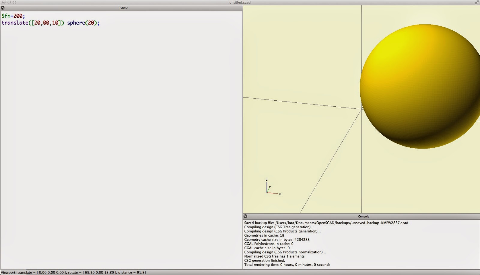
If you want to make a nicer sphere you can change the facet resolution, that is, raise or lower the number of polygons used to make up your object. You can also translate the sphere. The code syntax is pretty obvious and you can learn everything you need to know with the online documentation for OpenSCAD. For example, you could type this:
$fn=200;
translate([20,00,10]) sphere(20);
Then your F5 output would be a more finely-constructed sphere, shifted over 20mm and up 10mm:
To export for 3D printing, just hit F6 instead of F5. Once it finishes compiling (which can take a while if you've set your resolution too high, so watch out), use File/Export/Export as STL to export the file.
Step 2: Set up some size parameters.
We'll need to use the diameter of a penny in this model, but we might as well make that a variable so that we can easily resize our model for larger and smaller coins later. Also notice to avoid RADIUS IS NOT DIAMETER confusion we'll define them both:
d = 19.05;// diameter of penny
r = d/2; // radius of penny
Step 3: Make a rounded box.
We'll do this by making eight small spheres (1/5 the radius of the penny), translating them around to the eight corners of a box that is a sized for the penny (a little more than 4/5 the radius of the penny), and then taking their convex hull with the OpenSCAD hull module. We're making this more complicated than necessary right now, with all these variables; however this will help us keep everything parametrizable for resizing later.
Step 4: Chunk your code into modules.
In OpenSCAD, a module is like a little sub-program. Splitting up your code into modules helps keep things organized and readable. Let's convert the rounded-cube code above into a module and a "render" that calls the module and makes the object. We'll also put our rounded-cube-specific variables into the module:
The parentheses in box_hull(); are where we would pass an argument to the box_hull code, if one were needed. Our box_hull module does not take any arguments, although it does use the global radius parameter r.
Step 5: Make three cylindrical holes.
The module cylinder_holes below makes four cylinders, each with radius equal to 70% of the radius of the coin, so that the coin cannot fall out of the holes. We made the cylinders a little longer than the box so that they would cut out clean holes. OpenSCAD does not like it when two objects share the same faces, so we we are making the cylinders longer so as to not have faces that coincide with the faces of the rounded cube object. Each cylinder is translated to be centered and then rotated so that the three cylinders lie in mutually perpendicular directions. The "#" in front of the cylinders is only for this demo; it makes the cylinders red so that we can see them even after they are removed. Finally, in the "render" section we use difference to remove the cylinders from the rounded cube.
Step 6: Are we done yet?
To test if we are done yet, we'll make a penny-sized cylinder (note that the thickness of a penny is 1.52mm). Looking closely at where the penny meets the trap, we see that there isn't enough room; the penny intersects the trap. So we have to add something...
Step 7: Make a spherical hole for the penny.
Actually I guess technically we're going to take away something, not add something. Specifically, we'll make a sphere just larger than the penny with a sphere_hole module and then remove it from the trap object. Notice that in the difference command, anything we add after the second line is also removed from the object on the first line.
Step 8. Make it pretty.
The edges of the cylinder holes are a little sharp, and a quick and easy way to bevel them is to remove some well-placed spheres to cut off the edges. Below we added a new cylinder_bevels module that places six spheres centered slightly outward from the faces of the trap, as shown below. Note that we've added cylinder_bevels to the list of things to be removed from box_hull in the difference command, and preceded that line by a "#" so we can see the spheres.
Step 9. We're done!
After removing our test objects and "#" tags, we can press F6 to do an export-ready compile of the object. Notice in the Console window that this process took 16 seconds. It also reports various numerical information about the vertices, edges, and faces of the mesh of the object. To export for printing, use File/Export/Export as STL.
Here is the full, final OpenSCAD code for the Penny Trap model:
// mathgrrl penny trap walkthrough //////////////////////////////////////////////////////////// // parameters ////////////////////////////////////////////// $fn = 24;// facet resolution d = 19.05;// diameter of penny r = d/2; // radius of penny //////////////////////////////////////////////////////////// // render ////////////////////////////////////////////////// difference(){ box_hull(); cylinder_holes(); sphere_hole(); cylinder_bevels(); } //////////////////////////////////////////////////////////// // testing (comment out before compiling) ////////////////// //#translate([0,0,-1.52/2]) cylinder(1.52,r,r); //////////////////////////////////////////////////////////// // module for beveling the side holes ////////////////////// module cylinder_bevels(){ b =.8*r; // radius of bevel sphere v =1.35*r; // distance for placing bevel sphere translate([v,0,0]) sphere(b); translate([0,v,0]) sphere(b); translate([0,0,v]) sphere(b); translate([-v,0,0]) sphere(b); translate([0,-v,0]) sphere(b); translate([0,0,-v]) sphere(b); } //////////////////////////////////////////////////////////// // module for the center hole ////////////////////////////// module sphere_hole(){ sphere(r+1); } //////////////////////////////////////////////////////////// // module for cylindrical hole shapes ////////////////////// module cylinder_holes(){ h=.7*r; // radius of cylinder holes rotate([0,0,0]) translate([0,0,-(r+5)]) cylinder(d+10,h,h); rotate([90,0,0]) translate([0,0,-(r+5)]) cylinder(d+10,h,h); rotate([0,90,0]) translate([0,0,-(r+5)]) cylinder(d+10,h,h); } //////////////////////////////////////////////////////////// // module for rounded cube shape /////////////////////////// module box_hull(){ s = .2*r; // radius of small corner spheres c = .8*r+1;// distance to centers of corner spheres hull(){ translate([c,c,c]) sphere(s); translate([-c,c,c]) sphere(s); translate([c,-c,c]) sphere(s); translate([c,c,-c]) sphere(s); translate([-c,-c,c]) sphere(s); translate([-c,c,-c]) sphere(s); translate([c,-c,-c]) sphere(s); translate([-c,-c,-c]) sphere(s); } }
To wrap up our Penny Trap series, here is a YouTube video from Kanal von aquauit showing a coin trap printing and enclosing the coin along the way:
On Day 307 we printed a Penny Trap. Printing the model is easy, but how do you make it in the first place? That is, how do you make a 3D design file for a Penny Trap that your printer can slice up and print? Today we'll design a simple model of a Penny Trap using the easy-to-use but surprisingly versatile design program Tinkercad. The model is a little simpler than the one we used on Day 307, with less beveling and finishing:
Using Tinkercad is FREE and you can run the software online in your web browser at www.tinkercad.com without downloading anything. The Tinkercad website has a series of short and simple Lessons that you can use to learn how to navigate, place objects, and make basic models. There are also plenty of videos and PDFs online to help you get started, or to use in a classroom setting as a reference or as pre-homework. Sign up for a free account, open a new blank design, and follow along as we make a Penny Trap step-by-step from scratch. We'll talk through each step very carefully so this walk-through can be used for absolute beginners. Along the way we'll learn how to place Geometric Shapes and Holes, use Community Shape Scripts, and Align and Group objects in Tinkercad.
Step 1: Make a penny.
Measure it yourself with calipers or check Wikipedia: A United States penny has diameter 19.05mm and thickness 1.52mm. We'll start by making a 3D model of the penny so that we can make sure our Penny Trap is sized correctly to hold it. In Tinkercad, select a Cylinder from the right column menu of Geometric Shapes and place the cylinder onto the Workplane. Then select the Ruler tool from the Helpers menu in the right column, and place it anywhere on your Workplane. The Ruler will make it so that every object you click has displayed dimensions that you can edit by typing. Click on the cylinder you placed earlier, and change the diameter and thickness dimensions to 19.05mm and 1.52mm, respectively.
If you want to be all fancy you can decorate this cylinder by downloading pictures of the front and back of a penny, doing a bitmap trace, saving in .svg format with Inkscape, and then importing into Tinkercad (see Day 109). Or you can just go to the public Tinkercad site for the Penny Trap design, copy the penny, and paste it into your design!
Step 2: Make a rounded cube.
We could build a rounded cube by starting with a cube and beveling off the edges, but that's tricky in Tinkercad. Luckily, many people in the Tinkercad community have contributed shape scripts that can be used to quickly build interesting objects, and one user, Tony, has contributed a Rounded Cube model that will be handy here. From the Community menu on the right, click through the different pages of available designs until you find the Rounded Cube. Select this object and place it on the Workplane. With a shape script object it is best to change dimensions from the object's special Inspector menu instead of from the Workplane, so click on the Width, Height, and Depth values and change them each to 21mm - just larger than our penny diameter of 19.05mm. Then select a value for Corner Radius that appeals to you. Larger values will make rounder corners; we chose 2mm.
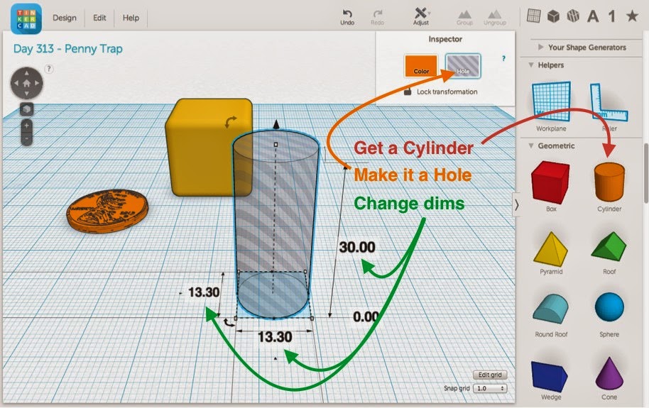
Step 3: Make a cylindrical window hole.
To make the windows through which we'll be able to see the trapped penny, we'll put three perpendicular cylindrical holes through the cube. Obviously each cylindrical hole has to have a smaller diameter than the penny, and they also have to be small enough for the cube to have sturdy side legs. Place a cylinder, make it a transparent "hole" with the aptly-named Hole button, and resize it to a diameter of 13.3mm and height of 30mm.
Step 4. Align and group three perpendicular window holes.
Now use Command-C and Command-V (or Control-C and Control-V if you're on a Windows keyboard) to make two more copies of the cylindrical window shape. If you click on one of the cylinders you will see three small arc arrows around the shape. Click on an arc arrow while holding down Shift and you will be able to drag-rotate the shape in increments of 45 degrees. Rotate two of the cylinder holes so that the three holes each point in different orthogonal directions. Then select all three cylinders (either by shift-clicking in sequence or by drag-selecting), click on the Adjust menu, and choose Align. While the Align tool is active you can click on the small alignment dots shown in the picture below to center the three cylinders with each other in all three directions. Finally, press the Group button to make one object out of your three centered cylinders.
Step 5. Align, group, and test.
Select the grouped cylinder window object and the rounded cube object and go to Adjust/Align to center the objects in all three directions. Press the Group button to merge the objects. We now have a box with holes through it! To test if the penny fits well in this trap, select the box-with-holes and the penny and Adjust/Align to center in all three directions. You'll see that the penny doesn't have enough room yet, so move the penny back off to the side.
Step 6. Make a sphere hole for the penny.
Place a Sphere on the Workplane, make it a Hole, and size it to be larger than the penny. We chose to make a sphere hole with a 20.5mm diameter. Then select both the sphere and the cube-with-holes, activate Adjust/Align, and press all three centering dots. Group the two objects together.
Step 7. Save your design as an STL file.
Delete the penny from your model, since we don't want to print that part. (You can do an "undo" after saving your file if you want the penny back afterwards.) Under the Design menu, choose Download for 3D Printing, and on the pop-up window select the file type STL. After it downloads you'll have to close the popup window yourself. You now have a model that is ready to print!
Step 8. Print!
Now you can print your Penny Trap on whatever 3D printer you have, pausing a little over halfway through to insert a penny. On the MakerBot Mini you should actually pause the print (it's hard to reach around the extruder assembly), but on the Replicator 2, Afinia H-Series, and some other printers you can sneak the penny in with a pair of long tongs or pliers while the print is in progress. We printed this model using .2mm/Standard layer height with raft but no supports, and increased the infill to 20% to get some "extra bits" to print inside the side legs of the model, as shown in the picture below. The extra infill helps to shore up any break lines at the height where the print was paused. Doubling the infill in this particular model only increased the print time by one minute, for a total print time of 27 minutes.
Next time: Designing the same thing from the ground up in OpenSCAD...
If your design is a solid hockey-puck bracelet shape and you print it with 0% infill, no roof, and no floor, then the raft will still print as a solid disk that uses more filament than the bracelet itself.
If you try to print a bracelet without a raft on the Mini, then you will have some pink spaghetti.
If your design is a solid hockey-puck shape with a smaller hockey-puck shape removed, then the mesh of the removed shape has to match up with the mesh of the large shape, if you want to try to print something thin.
If your design is a thin extruded curve to be used as a bracelet, don't make it too thin; the printer will try to make it as thin as you designed it.
Layer height and nozzle width are not the same thing.
Don't be cheap and make the raft super small, or the bracelet will rip when you take it off the raft.
The cosine of 0 is 1, but the sine of 0 is 0 and will kill everything.
If you use linear_extrude in OpenScad with too many slices, then the model won't slice well and will have strange artifacts when it prints.
Today we had a hankering for some knots, and wanted to try building something big on the Mini. We chose fredhohman's trumpety Trefoil knot model from Thingiverse. Fred Hohman is a student at the University of Georgia who studies fibered knots with Dr. David Gay. This print is at the maximum possible scale that can be printed on the Mini; it's 120mm (nearly five inches) long:
Settings: Printed on a MakerBot Replicator Mini with 4 shells and no infill, with raft and support. It didn't come out perfectly because that sort of setting does not include support on the inside/non-infill part of the model, so the print was full of gaps along the top-facing surfaces:
Next time I'll print this with standard solid settings instead of trying to be fancy. If I ever find the time to learn how to use Blender or Maya, I'll try to use them to surface-ify this model and make it a shell in a smarter way that can involve proper supports. If anyone reading this knows how to do that, please tell me about it in the comments or send me email.
Technical notes, math and Mathematica flavor: Fred Hohman will be guest-posting later this summer to tell us about the mathematics behind his fibered knot, and how he created it using Mathematica. According to his Thingiverse site he used RegionPlot3D, which looks like a promising method for other future mathy prints!
Today (July 2) I gave two public lectures about mathematics and 3D printing at MoMath, the National Museum of Mathematics, as part of their Math Encounters series. I brought along my Replicator 2 for a 3D-printing demonstration, but an hour before I had to leave for the talk, I hit a snag. In our old place in Virginia, I kept my filament on a shelf and fed it into the printer from there. Now I was in NYC, with everything I owned in the world packed up into a seemly endless collection of boxes - and no spool holder. I needed to print a spool holder in one hour! Let's use this as an excuse to show how to use Thingiverse and Tinkercad to easily remix existing designs. Here's what I did in this particular case:
Search on Thingiverse for "replicator filament spool", to find spencers's Filament Spool Holder design.
Download the design and open in MakerWare/Desktop. A print Preview showed that this design takes more than an hour to print, so we needed to remix somehow for time.
This particular file was only available on Thingiverse as a .thing file (I think these are now called .makerbot files?), which is only readable to MakerWare/Desktop. However with File/Save from the main menu at the very top of the screen you can choose to save the file as an STL, so that other programs can read the file.
Open up a new design in Tinkercad and use Import to load in spencer's design.
In this case the remix was extremely simple: we just added a cylindrical "hole" shape (see the picture below) and then grouped that shape with the original object to make it shorter.
In Tinkercad, use Design/Download for 3D Printing and save the new object as an STL file. A print Preview showed this shorter version would take just under an hour.
Now load the remixed file into Makerware/Desktop and print! We printed it, left it on the build plate, and put the machine into its travel box with the extruder still hot. Definitely the most stressful print I've done so far!
Here is the spool holder in action at the talk. It's in the back of the Replicator 2 in the foreground, which is printing the knot 10_125 (see Day 11) that is pictured on the big screen. More importantly, this is a picture of Jenny Lawton, the President of MakerBot Industries, who gave some remarks at the event!
During the talk we all constructed Level 0 Menger cubes out of business cards, to kick off the Level 3 Menger cube build at MoMath this October that will be part of the MegaMenger Level 4 build worldwide. Here's everyone at Math Encounters holding up their Level 0 cubes:
If you're interested in being a part of the giant worldwide MegaMenger build either as a volunteer or a contributor of business cards for the project, you can record your interest at megamenger.com. Help us a set a record for the world's largest business-card Menger cube!
July 1 was our first day in our new Brooklyn digs, so to celebrate we have made MrCainScience's Brooklyn Green Roof Design on Thingiverse. He made this model with Tinkercad, and was kind enough to post a link so that other people can copy and tinker with the model themselves. Tinkercad is a free online in-browser CAD program that is extremely simple and intuitive to use. We've had workshops in the 3-SPACE classroom where we taught twenty 8-year-olds how to use Tinkercad at the same time in less than an hour. Tinkercad also has online Lessons for learning how to use the basic controls and various modeling methods. We took MrCainScience's model and made a larger hole in the top so we could use it as a planter for some wheat grass that is now on our windowsill overlooking some Actual Brownstones:
Settings: Printed on a MakerBot Replicator Mini using Standard/default settings with Layer Height increased to .3mm, with Raft but no Support. This is our new favorite "standard" setting for the Mini. We printed the model at 80% so that it would fit on the build platform. The print took a long time but in the end it came out quite nicely.
Today* we move out of our house in Virginia, and I say goodbye (for now) to James Madison University. I'll be on leave for at least the next year while I am the Mathematician-in-Residence at MoMath, the National Museum of Mathematics. As a goodbye (for now) present to JMU, today I'm publicly posting the design for the infamous "JMU cube" business card holder that we've printed so many times in the JMU 3-SPACE classroom and the JMU MakerLab in Math/Stat.
If you want to create other JMU-shaped objects then you can also download 3D-printable verions of the official JMU font-logo, or the individual letters J, M, and U in that font. Add them to your favorite 3D model to make a JMU-flavored remix!
Settings: The cube and the letters print well with layer height .3mm/low on both the MakerBot Replicators and the Afinia H-Series Printers.
Design notes, Illustrator/Tinkercad flavor: The logo and letters for this design were based on the official JMU letter mark. We loaded the official image into Adobe Illustrator and extracted outlines of the logo letters. We also made a backwards-leaning "J" to use in the cube model. The modified letters were then extruded in Tinkercad, and each letter was grouped in various ways with other letters as “holes” to make the final design. That makes it sound kind of easy, but this model went through four different revisions, with each revision taking 1-2 hours of design time. You can open the model in Tinkercad and repeatedly un-group the model to see how it was put together. The cube was originally going to mimic the Godel, Escher, Bach cover design, but the "J" and "U" matched up so nicely across from each other that we went with that instead.
* Footnote: "Today" of course meaning June 30, which I am pretending it is right now while I am writing this post from the future. In the future future nobody will care that I am writing this past post from the past future. Present-people please bear with my procrastination-fueled time wrangling so that the blog will make sense to future-me.
This is the sixth in a series of posts about getting started from scratch with 3D printing. Our posts so far have focused on the mechanics of printing a simple model with various types of settings on the MakerBot Replicator Mini:
Day 303 - Rotating, scaling, previewing, and printing a simple octopus model
Day 304 - Adjusting layer height and infill to save time and money
Day 305 - Creating a custom slicing profile to adjust raft and floor
Day 306 - Using scaling and custom slicing to remix a model for a new purpose
Today we'll print a model that is particularly good for a first-day print in a 3D-printing class: a Penny Trap. Halfway through printing you Pause the printer and insert a penny into the model. Students love doing this, and it's a fun model for them to take home and show off to their friends and family after class.
The Penny Trap a great example of the difference between the additive nature of 3D printing (where a form is built up from nothing) and the subtractive nature of other manufacturing methods (where forms are cut out of existing blocks of material). With subtractive manufacturing it would not be possible to construct this model, because the penny cannot be inserted through the holes. However, with additive manufacturing we can add the penny during the print, forever trapping it inside!
Going further: If you want to make traps for different coins, you can find models sized for many major currencies, or even customize your own, with the Customizable Coin Trap model on Thingiverse.

.JPG)
.JPG)


.JPG)


.JPG)
.JPG)

.JPG)
.JPG)
.JPG)


.JPG)


.JPG)
.JPG)
.JPG)


.JPG)


.JPG)

