One last print for C's Pokemon addiction: jessed's Pokemon Deck Box on Thingiverse.
Thingiverse link: http://www.thingiverse.com/make:81427
Settings: MakerBot Replicator 2 with .3mm/low and a raft, on blue painter's tape on a glass build platform.
Technical notes, printing flavor: For some reason large, flat things tend to print out all stringy on my Replicator 2. This isn't a new thing; we've had this problem since at least as far back as when we were printing Menger Coasters on Day 121 and Day 122. The situation improves if I switch to .2mm layer resolution, but does not go away entirely. The weird thing is the the rafts print perfectly, with flat, beautiful surfaces. If you know why this happens and what setting or technique will help, please let me know!
Welcome to MakerHome
We've completed our yearlong print-a-day project!
All new material is now at Hacktastic: www.mathgrrl.com
Thursday, June 5, 2014
Wednesday, June 4, 2014
Day 282 - Must print all the Pokemon
Can you print just two Pokemon models for a 9-year-old? No. Two is not enough. You must print many, many Pokemon and then also print a full set for a friend's birthday. Today we are joined by FLOWALISTIK's Low-Poly Squirtle and Low-Poly Totodile models from Thingiverse. I'm really impressed with all four of these models. They are each designed to print perfectly without support and utilise extremely efficient choices of low-poly faces. Great design work by FLOWALISTIK, just please don't make me print any more of these right now.
Thingiverse link for (blue) Squirtle: http://www.thingiverse.com/thing:319413
Thingiverse link for (red) Totodile: http://www.thingiverse.com/thing:341719
Settings: Replicator 2 on .3mm/low, as usual.
Thingiverse link for (blue) Squirtle: http://www.thingiverse.com/thing:319413
Thingiverse link for (red) Totodile: http://www.thingiverse.com/thing:341719
Settings: Replicator 2 on .3mm/low, as usual.
Tuesday, June 3, 2014
Day 281 - Low-Poly Charmander and Bulbasaur
Pokemon fever has recently gripped my son's group of friends and now everything is about Pokemon cards more cards gotta get the best cards. As a surprise I printed FLOWALISTIK's lovely Low-Poly Charmander and Low-Poly Bulbasaur models for C, to celebrate his last week of school. These prints are expertly designed with about the lowest poly/face count that a model could have while still evoking Charmander and Bulbasaur. Very cool!
Thingiverse link for (green) Bulbasaur: http://www.thingiverse.com/thing:327753
Thingiverse link for (orange) Charmander: http://www.thingiverse.com/thing:323038
Settings: MakerBot Replicator 2 on .3mm/low with a raft, on blue tape on glass.
Thingiverse link for (green) Bulbasaur: http://www.thingiverse.com/thing:327753
Thingiverse link for (orange) Charmander: http://www.thingiverse.com/thing:323038
Settings: MakerBot Replicator 2 on .3mm/low with a raft, on blue tape on glass.
Monday, June 2, 2014
Day 280 - USAMO champion prints
Today I had the pleasure of meeting the 2014 USA Mathematical Olympiad champions at their awards celebration at the headquarters of the Mathematical Association of America in DC. We kicked off the day with a 3D-printing workshop. The students worked in four teams to design objects that would be printed later in the day. Most of the students had no design experience at all, but in under an hour they had collaborated to design some great things:
Three of the four models were made in Tinkercad. The spheres and half-spheres were made while the students learned how to use the Align and Hole tools. The figures with arms in the air were designed with extensive use of the Ruler tool and hand-calculated distances. The rockets were a minor miracle, as the students had decided to make one rocket that fits inside another and had to make a good guess for the amount of clearance/tolerance. They only had one try to make that guess, but they hit it square on the nose! The small rocket clicks into the large rocket beautifully.
The twisted square pyramid was made in OpenSCAD by a group in which one student had done some preliminary work (see Day 279). After a back-of-the-napkin calculation and some fights with compiling errors, this is what they made:
At the time I was helping all four groups and so didn't have a chance to ask the students about their construction, so let's take a moment to deconstruct it now. Their model is clearly a stack of rotated squares, each higher than the other and with corners on the edges of the supporting square. The part that needs calculating is determining how much to scale each square so that its corners align with the square below. From the students' code we can see that they are using a scaling factor sc determined by the ratio of the sum of the cosine and the sine of the angle of rotation. Why did they do that? Using some basic trigonometry we can draw out the following:
Once the picture is drawn there isn't much to do; the only thing you have to start with is the angle alpha and the original side length of 1. With a little trigonometry you can figure out the lengths of the legs a and b in the diagram, but what you really want it is the new side length h. The key insight is to realize that a + b = 1 so that you can solve for h, which becomes the scaling factor.
The USAMO students are some of the smartest, quickest math students in the nation. The top scorers will go on to represent our country in the International Mathematical Olympiad. They will go to college pretty much wherever they want to. They've worked amazingly hard to get to the level they are at, including taking extra courses and training workshops from organizations like the Art of Problem Solving. When they see a problem to solve they dive in fearlessly. They are curious, relentless, driven. Obsessive, even. In other words, they already think like mathematicians. Most importantly, like all mathematicians, they are experts in something that most people are terrible at, and it's not what you think it is; it's not calculating, or reasoning, or number sense, although they probably have all that as well. It's being able to be WRONG. To fail. To be stuck, confused, and lost. And then to get back up again and find another way around the problem.
One reason I was particularly excited to run a 3D-printing workshop with the USAMO champions was because I knew that most of them would have tons of mathematical experience, but no experience at all with 3D printing or design. These students are used to being the best. Not the best in their class or the best in their school, or even the best in their state. The best in the country. And competing with the best in the world. They are used to success. But in a 3D-printing workshop the playing field is level again, and the USAMO students struggled with basic alignment issues, design problems, and coding syntax just like all my other 3D students do.
Sometimes in my job as a math professor I see students who were rock stars in high school burn out once they get to college and are faced with new mathematics that they don't already know how to do. Those students somehow go from being experts at failing and problem-solving to being unable or unwilling to be stuck or feel stupid. The USAMO champions are at the top of their game and I wanted to remind them that they can still try new things and fail when they have to. And they did a great job of it. :)
UPDATE: Katherine Merow wrote a nice article for the MAA News about this called USAMO Winners Celebrated - and Challenged.
Sunday, June 1, 2014
Day 279 - Pre-USAMO prints
Today we are firing up our travel Afinia H-Series to get ready for tomorrow's 3D-printing workshop at the USA Math Olympiad award ceremony at the MAA Headquarters in Washington DC. The twelve student champions will each be designing and/or printing a 3D model at the workshop. One student did his homework, learned how to use OpenSCAD in advance, and then emailed me a snowman design he made from scratch. Here is his code:
x = 8.0;
module nose() {
color("orange") scale([3, .5, .5]) sphere(5);
}
module eye() {
color("black") sphere(2.5);
}
module face() {
translate([11, 0, 0]) nose();
translate([x * 1.55, x * .5, x * .5]) eye();
translate([x * 1.55, -x * .5, x * .5]) eye();
}
module body() {
sphere(25);
translate([0, 0, 30]) {
sphere(20);
translate([0, 0, 25]) {
sphere(15);
}
}
}
module arm() {
color([.6, .3, 0, 1]) {
cylinder(20, 1.5, 1.5);
}
}
module snowman()
{
union() {
color([.7, .7, 1, 1]) body();
translate([0, 0, 55]) face();
translate([4, 16, 37.5]) rotate([-135, -45, 0]) arm();
translate([4, -16, 37.5]) rotate([135, -45, 0]) arm();
}
}
translate([0, 0, 16]) intersection() {
color([.7, .7, 1, 1]) translate([-50, -50, -16]) cube([100, 100, 90]);
snowman($fn = 100);
}
I printed this model on the Afinia today, but the arms didn't get supported (maybe they were too small to be detected by the slicing software as needing support?), so they printed as little fuzzy pom-pons instead of looking like proper sticks. I added the following to the OpenSCAD to support the arms with tall truncated cones that can be cut off later:
// add arm support poles
translate([14,-30,0]) cylinder(h=45,r1=3,r2=1);
translate([14,30,0]) cylinder(h=45,r1=3,r2=1);
And here is the result:
Settings: Printed on an Afinia H-Series with super bling Build-Tak and glass build plate. If you look closely at the back of the build plate you can see two of walter's Customizable Platform Clips from Thingiverse holding down the glass build plate. The usual binder clips were too small to fit around the glass build plate so I printed walter's customized clips with the following settings:
One of the things I like most about the Afinia is its opaque white ABS filament; it looks so smooth and matte, never shiny. Perfect for a snowman! On the other hand, for something detailed like the Videogame Die all the way back from Day 12 that another of the USAMO students requested, the MakerBot Replicator 2 is the way to go:
Thingiverse link: http://www.thingiverse.com/make:80345
Settings: Printed on a MakerBot Replicator 2 with .3mm/low settings and raft, but NO supports. NOT using supports is key, because supports will fill up the designs on at least two sides of the die and be impossible to remove afterwards.
UPDATE: The student that did his homework turned out to be Joshua Brackensiek from Arizona College Prep-Erie, who got a perfect score on the USAMO this year. He also turned out to be a lovely person and it was a great pleasure meeting him and his mother at the award ceremony.
x = 8.0;
module nose() {
color("orange") scale([3, .5, .5]) sphere(5);
}
module eye() {
color("black") sphere(2.5);
}
module face() {
translate([11, 0, 0]) nose();
translate([x * 1.55, x * .5, x * .5]) eye();
translate([x * 1.55, -x * .5, x * .5]) eye();
}
module body() {
sphere(25);
translate([0, 0, 30]) {
sphere(20);
translate([0, 0, 25]) {
sphere(15);
}
}
}
module arm() {
color([.6, .3, 0, 1]) {
cylinder(20, 1.5, 1.5);
}
}
module snowman()
{
union() {
color([.7, .7, 1, 1]) body();
translate([0, 0, 55]) face();
translate([4, 16, 37.5]) rotate([-135, -45, 0]) arm();
translate([4, -16, 37.5]) rotate([135, -45, 0]) arm();
}
}
translate([0, 0, 16]) intersection() {
color([.7, .7, 1, 1]) translate([-50, -50, -16]) cube([100, 100, 90]);
snowman($fn = 100);
}
I printed this model on the Afinia today, but the arms didn't get supported (maybe they were too small to be detected by the slicing software as needing support?), so they printed as little fuzzy pom-pons instead of looking like proper sticks. I added the following to the OpenSCAD to support the arms with tall truncated cones that can be cut off later:
// add arm support poles
translate([14,-30,0]) cylinder(h=45,r1=3,r2=1);
translate([14,30,0]) cylinder(h=45,r1=3,r2=1);
And here is the result:
Settings: Printed on an Afinia H-Series with super bling Build-Tak and glass build plate. If you look closely at the back of the build plate you can see two of walter's Customizable Platform Clips from Thingiverse holding down the glass build plate. The usual binder clips were too small to fit around the glass build plate so I printed walter's customized clips with the following settings:
- _platformGap = 7.2
- _wallThickness = 1.0
- _style = square
- _diameter = 2.2
- _length = 16
One of the things I like most about the Afinia is its opaque white ABS filament; it looks so smooth and matte, never shiny. Perfect for a snowman! On the other hand, for something detailed like the Videogame Die all the way back from Day 12 that another of the USAMO students requested, the MakerBot Replicator 2 is the way to go:
Thingiverse link: http://www.thingiverse.com/make:80345
Settings: Printed on a MakerBot Replicator 2 with .3mm/low settings and raft, but NO supports. NOT using supports is key, because supports will fill up the designs on at least two sides of the die and be impossible to remove afterwards.
UPDATE: The student that did his homework turned out to be Joshua Brackensiek from Arizona College Prep-Erie, who got a perfect score on the USAMO this year. He also turned out to be a lovely person and it was a great pleasure meeting him and his mother at the award ceremony.
Saturday, May 31, 2014
Day 278 - Silver pentagonal hexacontahedron bracelet
Back on Day 218 we printed a bracelet built by extracting the center rings of a Pentagonal Hexacontahedron in TopMod. This week we finally received the stainless steel version we ordered from Shapeways, and it is beautiful!
It's pretty bulky so it isn't cheap, and you have to physically bend it open to get it on, then closed to make it tight again (although repeated bending does not seem to have any ill-effects so far). If you want to purchase one you can do so at the Shapeways link below. Or you can download my file from Thingiverse and print one for free on your own machine!
Thingiverse link: http://www.thingiverse.com/thing:288182
Shapeways link: http://www.shapeways.com/model/1860381/pentagonal-hexacontahedron-bracelet.html
Settings: For printing yourself, see Day 218. For Shapeways, just choose the metal that you want and they will do the rest.
Friday, May 30, 2014
Day 277 - Friday Fail: Diameter-is-not-radius edition, with Customizable Power Hair Clips!
Say it with me now: If you measure across a cylinder with calipers, you get the diameter. The DI-AM-E-TER. Not the radius. Just saying, giant-model-on-the-right:
As you can see, today we printed some power hair clips. Welcome to a special Ladies' edition of Friday Fail! To illustrate why custom hair clips might be necessary I am going to break a personal rule and show you a picture of myself. Note the mountain of unreasonable hair. It's impossible to tie up with regular barrettes and clips. It does not obey.
Only a few types of store-bought clips will keep this mess of hair up. Even those that work at first end up breaking within a week or two. Like all accessories and clothing for me, nothing works exactly the way I need it to work. (Side note: It was only yesterday that I put on the first piece of women's clothing that ever actually fit me in my entire adult life. It was from eshakti.com, who will make clothes to custom-fit you given whatever measurements you provide. Until yesterday I thought that *I* was the wrong shape. Turns out it was the *clothes* that were the wrong shape. Screw you, clothes. #yesallwomen)
Anyway, today I designed a power hair clip that can tame even my monster hair. The design is based on an old clip of mine that sort of worked for a while and now I can't find anywhere.
Here are two of the clips in action. The fact that only two of the clips were needed here is itself a miracle; I'm usually tied up with five or six store-bought clips:
These power hair clips were made in OpenSCAD with some mesh management in TopMod afterwards to smooth them up a bit. Since your hair isn't my hair, I also put a parametric OpenSCAD model on the Thingiverse Customizer so you can eshakti it up yourself.
Thingiverse link: http://www.thingiverse.com/thing:354313
Settings: Printed on a MakerBot Replicator 2 on .3mm/low setting. Raft is not strictly necessary even over tape-on-glass, but if you're going to print multiple copies at once and your platform doesn't level completely then I recommend a raft.
Technical notes, hack flavor: Yes, this model is a hack. I made it by defining a sequence of coordinates that connected up into the basic shape that I wanted, which is why it looks all jagged and unprofessional. On the other hand the clips will be mostly buried under piles of hair so it really doesn't matter! The pre-made small and large power clip models were remeshed to be smoother in TopMod, using two applications of "Doo Sabin" with "Check for multiple edges" selected. (Note: TopMod can't import STL files but it will import OBJ files, which you can export from MeshLab; however for some reason TopMod *can* export STL files, so at least you won't have to convert back afterwards.) If you make custom sizes in the Customizer then you'll have to do your own remeshing or enjoy a more choppy look. Here's what the large clip looks like before the double Doo Sabin:
And here's what it looks like after we press "Perform Remeshing" a couple of times:
Technical notes, trig flavor: There is some nice basic trigonometry in the construction, specifically this: If you want to make some coordinates around a circle, use the fact that each point on the circle can be expressed as (r*cos(angle),r*sin(angle)), where r is the radius (RADIUS NOT DIAMETER) of the circle and the angle is measured between the positive side of the x-axis and the line from the origin to the desired point on the unit circle. See Math Open Reference for more details on the math involved. In OpenSCAD angles are measured in degrees instead of radians which can be kind of a pain, so instead of using the OpenSCAD sine and cosine functions I just computed the trig values myself; for example cos(45 degrees) = sqrt(2)/2. The first six points in the code below are around a circle of radius loop_radius, and the remaining points trace out the clip itself.
Thursday, May 29, 2014
Day 276 - Petal conformation of 6_2
Today is my favorite from the 3D-Printed Conformations of Knots through 7 Crossings series that my Math 297 students developed last semester in the JMU 3-SPACE classroom. It's a petal knot conformation of 6_2, which means that there is an angle from which all of the crossings line up on top of one another to form a single daisy-like crossing. Colin Adams of Williams College, together with an army of amazing students, proved recently that every knot has a petal conformation. They also came up with explicit constructions for some of those conformations, one of which we used to print today's model:
Thingiverse link: http://www.thingiverse.com/make:80268
Settings: Printed on a Replicator 2 with our usual custom knot slicing profile.
Technical notes, Mathematica flavor: Today's petal knot was designed and printed by JMU Student Jonathan Gerhard, using the method from Day 152 and data sent to us by Adams' student Daniel Vitek. Here's Jonathan's walkthough of what he did:
The data for the petal knot conformation of 6_2 came in the form of 500 points in space determined by the following Mathematica code:
Bumps[t_, n_] := If[Abs[Mod[t, n, -n/2]] > 1, 0, Cos[Ï€*Mod[t, n, -n/2]/2]^2];
BumpSum[p_, t_] := Sum[p[[i]]*Bumps[t + 1 - i, Length[p]], {i, 1, Length[p]}];
PetalPlot[p_] := ParametricPlot3D[{
Sin[Ï€*t]*Cos[Ï€*t/Length[p]],
Sin[Ï€*t]*Sin[Ï€*t/Length[p]],
BumpSum[p, t]},
{t, 0, Length[p]}];
p = {1, 3, 5, 2, 8, 4, 7, 9, 6};
points = N[{Sin[Ï€*t]*Cos[Ï€*t/Length[p]], Sin[Ï€*t]*Sin[Ï€*t/Length[p]],
BumpSum[p, t]} /. ({t -> #} & /@ (Range[0, 500]/500*Length[p]))];
ListPointPlot3D[points]
To get a smooth representation we could just use Tube in Mathematica, as follows:
Graphics3D[Tube[points, .075]]
This looked good, however, it was very tall. So I modified it by changing the BumpSum[p, t]} in PetalPlot[p_] to 0.26BumpSum[p, t]}to make the height smaller.
Mathematica models can sometimes export badly, so instead of using the Tube model above I used the OpenSCAD technique we've been using for our data-defined knots (see for example Day 272). To do this, I first had to open the 500 Mathematica datapoints in TextEdit and run a "Find and Replace" to change all “{“s to “[“ and all “}” to “],”s. Then I input the reformatted data points into the following OpenScad code (not all of the points are included here because there are so many!):
Paths = [[
[0., 0., 0.26],[0.05651741885454146, 0.00035511408887296787, 0.26041559697166655],[0.11284747420775955, 0.0014181578334111625, 0.2616610592647978],[0.16880345185324083, 0.0031822470046126636, 0.2637324052612605],[0.22419993383963085, 0.005635945627807872, 0.2666230130754899],[0.27885344076990115, 0.008763322416738774, 0.27032364172399476],
%...lots of data points
[-0.27885344076990115, 0.008763322416738774, 0.28580910430998696],[-0.22419993383963085, 0.005635945627807872, 0.27655753268872485],[-0.16880345185324083, 0.0031822470046126636, 0.26933101315315133],[-0.11284747420775955, 0.0014181578334111625, 0.2641526481619946],[-0.05651741885454146, 0.00035511408887296787, 0.26103899242916623],[0., 0., 0.26],[0.05651741885454146, 0.00035511408887296787, 0.26041559697166655],
]];
// Sides of the tube
Sides = 30;
// Radius of tube
Radius = .1;
//Scale of knot
Scale= 3;
Colors = [[1,0,0],[0,1,0],[0,0,1],[1,1,0],[1,0,1],[0,1,1]];
module disc_p2p(p1, p2, r) {
assign(p = p2 - p1)
translate(p1 + p/2)
rotate([0, 0, atan2(p[1], p[0])])
rotate([0, atan2(sqrt(pow(p[0], 2)+pow(p[1], 2)),p[2]), 0])
render() cylinder(h = 0.1, r1 = r, r2 = 0);
};
module knot_path(path,r) {
for (t = [0: 1: len(path)-1 ])
assign (p0 = path[t],
p1 = path[(t + 1) % len(path)],
p2 = path[(t + 2) % len(path)] )
hull() {
disc_p2p (p0,p1,r);
disc_p2p (p1,p2,r);
}
};
module knot(paths,r)
for (i = [0:1:len(paths)-1])
color(Colors[i])
knot_path(paths[i],r);
$fn=Sides;
scale(Scale)
knot(Paths,Radius);
Compile and render this by hitting “F6”. Once it finishes (which will take forever), go to the OpenSCAD Design menu and choose “Export as STL”. And you’re done!
Wednesday, May 28, 2014
Day 275 - Mosaic conformation of 6_1
Today's knot print is a mosaic projection of 6_1:
Thingiverse link: http://www.thingiverse.com/make:80243
Settings: Printed on a Replicator 2 with .3mm/low and normal support settings.
Technical notes, math flavor: This knot was designed and printed by JMU Student Taylor Meador. The images in her description below are from slides of a Knot Mosaic talk from Lew Ludwig of Denison College.
A mosaic projection of a knot is one that can be constructed as a mosaic using any of the 11 possible mosaic tiles:
We say that a mosaic projection is n-mosaic if it can be enclosed in an nxn square, and that the mosaic number of a knot is the minimum n such that the knot has an n-mosaic projection. The mosaic number for today's knot 6_1 is 5, and our conformation is taken from the figure below right:
Interestingly, as you can see in the figure, in order to realize a 5-mosaic projection of 6_1 we had to use an inefficient projection with seven crossings instead of six. In other words, in order to achieve a minimal mosaic number we had to use a projection with a non-minimal crossing number.
Technical notes, OpenSCAD flavor: Taylor designed this model in OpenSCAD based on kitwallace's minimal stick code by constructing (x,y,z) corner coordinates near the crossings, based on the picture above right. She describes her process as follows:
The code is a list of coordinates interpreted directly from the 2D 6_1 mosaic. We added coordinates one at a time to make a path around the knot. I reinterpreted the 5 x 5 mosaic board as an (x,y) coordinate plane in OpenSCAD, with each mosaic tile edge representing 4 units on the (x,y) plane. I used the z-coordinate to allow the knot to pass over or under itself at the crossings; overcrossings simply remained at level z=1, and undercrossings were adjusted to z=0. For example, traveling across one mosaic tile from left to right while following an undercrossing would result in coordinates that move across, then down, then across, then up, then across:
(x,y,1) --> (x+1,y,1) --> (x+1,y,0) --> (x+3,y,0) --> (x+3,y,1) --> (x+4,y,1).
The a and b parameters in the code allow us to scale the (x,y) plane separately from the z-axis, so that we can better adjust the clearance around and inside the crossings.
Tuesday, May 27, 2014
Day 274 - Customizable Sock Bones
Sometimes I think I got into this 3D printing thing just so I would have the opportunity to say things like "customizable sock bones". Here they are:
These dogbone-like objects are for holding pairs of socks together, so you don't have to roll or tie up your socks. My sock drawer used to be an unholy mess of partnerless socks, but now it looks like this:
Let's be honest, though. If my sock drawer was really going to look like this then I wouldn't need any clips. After rummaging around it actually looks like this:
That's at least a thousand times better than its previous state, which I am not going to show you. The sock bones shown in these pictures work for standard men's socks, folded in half and then clipped in the middle. At the link below you'll also find a Customizer model that you can adjust to your size of socks.
Thingiverse link: http://www.thingiverse.com/thing:352805
Settings: Printed on a MakerBot Replicator 2 at .3mm/low. Printing six at a time takes about an hour, and it's a good way to use up scraps of filament you have lying around.
Technical notes, OpenSCAD flavor: This model is really simple; just a 2D shape made of circles and rectangles, extruded into 3D using linear_extrude.
// mathgrrl customizable sock bone
/////////////////////////////////////////////////////////////
// parameters ///////////////////////////////////////////////
// Length from one side of the sock to the other
length = 86;
// Width/thickness of the folded sock
width = 13;
// parameters that the user does not get to specify
$fn = 24*1;
radius = width*(8/13);
thickness = 2*1;
height = 10*1;
/////////////////////////////////////////////////////////////
// renders //////////////////////////////////////////////////
sockbone();
/////////////////////////////////////////////////////////////
// module for clip //////////////////////////////////////////
module sockbone(){
linear_extrude(height)
// 2D shape of bone holder
union(){
difference(){
// outer bone
union(){
translate([radius,0,0])
circle(radius);
translate([radius,-width/2,0])
square([length-2*radius,width]);
translate([length-radius,0,0])
circle(radius);
};
// take away inner bone
union(){
translate([radius,0,0])
circle(radius-thickness);
translate([radius,-(width-2*thickness)/2,0])
square([length-2*radius,width-2*thickness]);
translate([length-radius,0,0])
circle(radius-thickness);
}
// take away opening
translate([.25*length,0,0])
square(.5*length);
}
// rounded end caps
translate([.25*length,width/2-thickness/2,0])
circle(.7*thickness);
translate([.75*length,width/2-thickness/2,0])
circle(.7*thickness);
}
}
Monday, May 26, 2014
Day 273 - Lissajous conformation of 5_2
Today's knot is 5_2, the three-twist knot, in a Lissajous conformation. The cool thing about this model is that from each side, the knot looks like a wavy cosine function:
Thingiverse link: http://www.thingiverse.com/make:80103
Settings: MakerBot Replicator 2 with our custom knot-slicing profile.
Technical notes, math flavor: Lissajous knots are knots that can be parametrized by a triple of simple cosine functions, and are a subclass of Fourier knots. Although every knot can be expressed as a Fourier-(1,1,k) knot, not every knot is a Lissajous knot, that is, a Fourier-(1,1,1) knot. In this notation the (1,1,k) denotes how many cosine terms the parametrization has in each coordinate; for example, a Lissajous knot is (1,1,1) so has just one cosine function in each coordinate, but our trefoil from Day 151 is Fourier-(1,1,2) because its z-coordinate parametrization is a sum of two cosine functions. Today's 5_2 knot is the first knot in the standard table that can be expressed as a Lissajous knot, with just one cosine function in each coordinate.
Technical notes, OpenSCAD flavor: This knot was designed and printed by JMU student Patrick Moran. We used the slow but effective OpenSCAD "tubify" code from Day 151, and the parameters and phase shift values for 5_2 from the Wikipedia entry on Lissajous knots. However, this parametrization is built for knots with zero thickness, which of course would not print very well. With the thickness we needed for printing, the Wikipedia parametrization is self-intersecting:
In the code above, the factors of 180/3.14159 convert the phase shifts into degrees, since OpenSCAD does not use radians. The scaling factor of 30 in each coordinate allows a large enough knot parametrization to accommodate our radius of r=1.5. To fix the self-intersection of the original parametrization, Patrick re-scaled each coordinate individually as follows:
Sunday, May 25, 2014
Day 272 - Lattice conformation of 5_1
The 
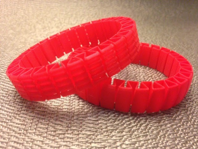
cinquefoil knot 5_1 is one of two 5-crossing knots. The conformation we chose for this knot is a <LINK>lattice conformation<LINK>, which means that it follows only perpendicular directions in 3-space. In other words, this conformation is obtained by connecting integer-valued coordinates in space with straight lines.
Thingiverse link: http://www.thingiverse.com/make:80077
Settings: Replicator 2 with our usual custom support settings for knots.
Technical notes, math flavor: This knot was made by JMU student Kirill Korsak, who has this to say about lattice knots:
The lattice stick number for a knot is the minimal number of line segments required to construct that knot on a cubic lattice. While a stick configuration of a knot can consist of sticks of differing lengths, a lattice configuration is thought of as a collection of sticks of unit length. This means that if a knot on the cubic lattice has an edge that extends from, say, (0,0,0) to (0,0,3), then that length-three edge is considered to be three unit-length sticks lined up from end to end. It generally takes many more line segments to create a minimal lattice knot than to create a minimal stick knot. In fact it was shown in 1992 by Diao that the minimal number of sticks required to build a non-trivial knot on a cubic lattice is 24 (and that all such knots are trefoils), where we saw on Day 269 that the knot 4_1 can be made from just 7 variable-length non-lattice sticks. Today's 5_1 lattice knot is realized with 34 lattice points and therefore the lattice stick number of 5_1 is at most 34. However, it has not yet been proven that this is the minimal lattice knot configuration for 5_1.
Technical notes, OpenSCAD flavor: Kirill made this lattice knot with a modification of kitwallace's Mathematical Knots to OpenSCAD code that Greg used on Day 269, using data for the 5_1 lattice configuration obtained from the Minimal knots on cubic lattices page hosted by Andrew Rechnitzer of the University of British Columbia. Here is Kirill's resulting code:
Paths = [[[2,2,1],[1,2,1],[0,2,1],[0,3,1],[0,4,1],[1,4,1],[1,4,2],[1,4,3],[1,3,3],[1,2,3],[1,1,3],[1,1,2],[1,1,1],[1,1,0],[1,2,0],[1,3,0],[1,3,1],[1,3,2],[0,3,2],[0,4,2],[0,5,2],[1,5,2],[2,5,2],[2,4,2],[2,3,2],[2,2,2],[1,2,2],[0,2,2],[0,1,2],[0,0,2],[1,0,2],[2,0,2],[2,0,1],
[2,1,1]]];
// Sides of the tube
Sides = 20;
// Radius of tube
Radius = 0.39;
//Scale of knot
Scale=20;
module knot_path(path,r) {
for (i = [0 : 1 : len(path) - 1 ]) {
hull() {
translate(path[i]) sphere(r);
translate(path[(i + 1) % len(path)]) sphere(r);
}
}
};
module knot(paths,r) {
for (p = [0 : 1 : len(paths) - 1])
knot_path(paths[p],r);
};
$fn=Sides;
scale(Scale)
knot(Paths, Radius);
Saturday, May 24, 2014
Day 271 - Stretchy bracelets
It's Saturday and we are resting. Kids keep asking me for stretchy bracelets so today I made some from owens' Smooth and ridged stretchlets model on Thingiverse. They came out great! I love the ridgy one and in fact wore one of them around all day today until it finally broke because am a fidget queen who kept flipping it inside-out and pulling it off and on again. Also I'm a liar because I actually printed these and wore them around on Wednesday 5/28 but I'm pretending that I did it four days earlier for this blog post.
Thingiverse link: http://www.thingiverse.com/make:79822
Settings: Printed on a Replicator 2 with .3mm/low resolution and a custom profile to get no roof, no floor, 0% fill, and only one shell around the outside. I used a raft but I'm pretty sure that it wasn't really necessary.
Friday, May 23, 2014
Day 270 - Friday Fail: Measure-twice-print-once edition, with Poker chip racks
Today I wanted to design and print a rack for poker chips, and I wanted it to hold three stacks of 20 poker chips. If you sew, or knit, or build, or pretty much do anything, then you know you that should measure carefully, and preferably at least twice. I measured the chips. I remembered to measure the chips in a stack in case that was somehow mysteriously different than 20 times the height of one chip. I measured it a few times to be sure and because I always forget the first measurement number while I am re-measuring and then have to measure again. I remembered to add a millimeter to account for tolerance. Everything is great; measure, measure. Except that then I wrote this code:
radius = 20+1; // radius of actual poker chip plus fudge
height = 67+1; // height of actual stack of 20 chips plus fudge
thickness = 2; // desired thickness of plastic
shift = 2; // to make clean holes and/or holes with edges
difference(){
// outside cylinder
translate([0,0,radius])
rotate(90,[0,1,0])
cylinder(h=height,r=radius+thickness);
// take away chip cylinder
translate([thickness,0,radius+thickness])
rotate(90,[0,1,0])
cylinder(h=height-2*thickness,r=radius);
// take away top
translate([-shift,-.5*(height+2*shift),radius+thickness])
cube(height+2*thickness+2*shift);
// take away thumb cylinder
translate([-shift,0,radius+thickness])
rotate(90,[0,1,0])
cylinder(h=height+2*thickness+2*shift,r=radius-3*thickness);
}
And no amount of good measuring can overcome stupid code. Yet another rookie mistake: I used the 20-chips-plus-tolerance dimension for the outside and then took a smaller hole out of that to put the chips in. The resulting fail is on the left in the picture below; it only holds 18 chips. There is also an earlier bonus fail on the right from when I thought it would be a smart idea to print the rack upside-down without a raft.
Luckily, stupid fails are usually easy to fix; here's the corrected 20-chip version, along with a suitably Friday-Fail poker hand:
The design is now on Customizer and you can use it to make poker chip racks with variable numbers of rows and chips. If you use different denominations of chips then you could make one of these for each player. We currently play with just one denomination of chips so we use the three-row rack to hold all the chips for a short family poker evening and store the two-row rack to use when guests join our game:
Thingiverse link: http://www.thingiverse.com/thing:350083?save=success
Settings: MakerBot Replicator 2 with .3mm/low, printed with no supports but with a raft, on a glass build platform with blue painters tape.
Technical notes, OpenSCAD Customizer edition: Below is the full code that was submitted to the Thingiverse Customizer. Notice that the parameters at the top are meant to be entered by the user. The comments above these parameters are used by Customizer as descriptions in the user interface. The last group of parameters will not be visible to Customizer users. Any parameter that is computed will be ignored by Customizer. If you want a parameter to be invisible but it doesn't require any computation then just multiply it by 1 when it is defined. In the final code I also added a line to flatten the bottom of the rack so that it would have better contact with the build platform and its eventual resting place on the table.
// mathgrrl customizable poker chip rack
/////////////////////////////////////////////////////////////
// parameters ///////////////////////////////////////////////
// Diameter of one poker chip (in millimeters)
Chip_Diameter = 20;
// Thickness of one poker chip (in millimeters)
Chip_Thickness = 3.35;
// Number of chips you want in each row of the rack
Number_of_Chips = 20;
// Number of rows you want in the rack
Number_of_Rows = 3;
// Thickness of the rack itself
Rack_Thickness = 2;
// Enter a tolerance (more if your chips are too tight, less if they are too loose)
Fudge = 1;
// Parameters invisible to the user
$fn = 96*1;
radius = Chip_Diameter/2 + Fudge;
height = Chip_Thickness*Number_of_Chips + Fudge;
thickness = Rack_Thickness*1;
rows = Number_of_Rows*1;
shift = 2*1; // to make clean holes and/or holes with edges
/////////////////////////////////////////////////////////////
// renders //////////////////////////////////////////////////
for (i = [1:1:rows]){
translate([0,(i-1)*(2*radius+thickness),0]) chipstack();
}
/////////////////////////////////////////////////////////////
// module for holding one stack of chips ////////////////////
module chipstack(){
// shift down to platform
translate([0,0,-.5])
difference(){
// outside cylinder
translate([0,0,radius+thickness])
rotate(90,[0,1,0])
cylinder(h=height+2*thickness,r=radius+thickness);
// take away chip cylinder
translate([thickness,0,radius+thickness])
rotate(90,[0,1,0])
cylinder(h=height,r=radius);
// take away thumb cylinder
translate([-shift,0,radius+thickness])
rotate(90,[0,1,0])
cylinder(h=height+2*thickness+2*shift,r=radius-1.5*thickness);
// take away top
translate([-shift,-.5*(height+2*shift),radius+thickness])
cube(height+2*thickness+2*shift);
// flatten bottom
translate([-shift,-5,-10+.5])
cube([height+2*thickness+2*shift,10,10]);
}
}
Thursday, May 22, 2014
Day 269 - Minimal stick conformation of 4_1
The figure-eight knot 4_1 is the only four-crossing knot, and it is usually drawn like the white knot on the left in the figure below. It is also the only knot whose stick number is 7, which means that the knot can be made out of 7 straight line segments, but no fewer. The tricky thing about studying stick numbers is figuring out how to prove the "but no fewer" part (see the Technical Notes below). Today's print is a 7-stick conformation of 4_1:
Thingiverse link: http://www.thingiverse.com/make:79819
Settings: Printed on a Replicator 2 with .2mm custom slicing profile.
Technical notes, math flavor: This knot was made by JMU student Greg Houchins, who put together the following nice survey of current known bounds on stick numbers:
The stick number of a knot is the minimal number of straight sticks joined together required to make a certain knot. More formally stated, it is the minimal number of edges of a polygon path that is equivalent to the given knot. This knot invariant becomes very difficult to compute for large crossing knots and there is no given formula that works for all knots. However, there have been some publications that have advanced the search for a universal formulation. Taek Jin published a paper in 1997 determining the stick number of torus knots, T(p,q) for relatively close p and q:
In 1991, Seita Negami was able to put a bound on the stick number, which he called broken line number, of knots proving that for a knot K with crossing number c(K) we have:
Jorge Calvo was able to raise the lower bound in his 2001 paper to
The upper bound was later improved further by Seungsang Oh and Youngsik Huh to
Technical notes, OpenSCAD flavor: To make the stick model of 4_1, Greg used kitwallace's amazing Mathematical Knots to OpenSCAD website, which generates OpenSCAD knot code based on data it pulls from The Knot Server. Here is Greg's description of the process:
To create a 3D model of a stick conformation, all we need to do is put spheres at the points where the sticks meet and then connect these spheres. Fortunately, not only are the coordinates of these sphere points available, but an OpenSCAD file is available implementing this idea at kitwalace.co.uk/3d/knot.xq. On this site, you enter the number that the knot is listed as in the Knot Atlas. The figure-eight knot 4_1 is the third knot in the Knot Atlas so we enter 3 as the "Knot Type". Then under the dropdown menu for render type, select stick, then press download, as shown in this screenshot:
When the resulting file is opened in OpenSCAD, the knot will be very thin and not suitable for 3D printing. To thicken the knot, you can adjust the radius parameter. However, the thicker knot may overlap itself. To change this we can manipulate the end points in order to open the knot up so that the sides no longer overlap. The code used for the model is as follows.
Knot_name = "Minimal stick candidate for 4.1";
Knot_type = "3";
Paths = [
[
[1.417090,-2.384662,-3.062703],//(+,-,-)
[-1.114094,3.107347,0.801322],//(-,+,+)
[-2.493145,-3.558361,2.356218],//(-,-,+)
[-0.108153,2.428202,-2.660958],//(0,+,-)
[3.607935,-4.376481,1.075724],//(+,-,+)
[-3.552488,-0.384435,-0.962569],//(-,-,-)
[3.922855,2.868389,1.952966]//(+,+,+)
]
];
// Sides of the tube
Sides = 20;
// Radius of tube
Radius = 0.38;
//Scale of knot
Scale=20;
Colors = [[1,0,0],[0,1,0],[0,0,1],[1,1,0],[1,0,1],[0,1,1]];
module knot_path(path,r) {
for (i = [0 : 1 : len(path) - 1 ]) {
hull() {
translate(path[i]) sphere(r);
translate(path[(i + 1) % len(path)]) sphere(r);
}
}
};
module knot(paths,r) {
for (p = [0 : 1 : len(paths) - 1])
color(Colors[p])
knot_path(paths[p],r);
};
$fn=Sides;
scale(Scale)
knot(Paths, Radius);
Once you are happy with the knot conformation, press F_6 in OpenSCAD to render the model in full quality so it can be exported.
Thingiverse link: http://www.thingiverse.com/make:79819
Settings: Printed on a Replicator 2 with .2mm custom slicing profile.
Technical notes, math flavor: This knot was made by JMU student Greg Houchins, who put together the following nice survey of current known bounds on stick numbers:
The stick number of a knot is the minimal number of straight sticks joined together required to make a certain knot. More formally stated, it is the minimal number of edges of a polygon path that is equivalent to the given knot. This knot invariant becomes very difficult to compute for large crossing knots and there is no given formula that works for all knots. However, there have been some publications that have advanced the search for a universal formulation. Taek Jin published a paper in 1997 determining the stick number of torus knots, T(p,q) for relatively close p and q:
stick(T(p,q)) = 2q, if 2<= p < q <= 2p.
In 1991, Seita Negami was able to put a bound on the stick number, which he called broken line number, of knots proving that for a knot K with crossing number c(K) we have:
(1/2)(5+sqrt(25+8(c(k)-2))) <= stick(K) <= 2 c(K).
Jorge Calvo was able to raise the lower bound in his 2001 paper to
(1/2)(7+sqrt(8c(K)+1)) <= stick(K).
The upper bound was later improved further by Seungsang Oh and Youngsik Huh to
stick(K) <= (3/2)(c(K)+1).
Technical notes, OpenSCAD flavor: To make the stick model of 4_1, Greg used kitwallace's amazing Mathematical Knots to OpenSCAD website, which generates OpenSCAD knot code based on data it pulls from The Knot Server. Here is Greg's description of the process:
To create a 3D model of a stick conformation, all we need to do is put spheres at the points where the sticks meet and then connect these spheres. Fortunately, not only are the coordinates of these sphere points available, but an OpenSCAD file is available implementing this idea at kitwalace.co.uk/3d/knot.xq. On this site, you enter the number that the knot is listed as in the Knot Atlas. The figure-eight knot 4_1 is the third knot in the Knot Atlas so we enter 3 as the "Knot Type". Then under the dropdown menu for render type, select stick, then press download, as shown in this screenshot:
When the resulting file is opened in OpenSCAD, the knot will be very thin and not suitable for 3D printing. To thicken the knot, you can adjust the radius parameter. However, the thicker knot may overlap itself. To change this we can manipulate the end points in order to open the knot up so that the sides no longer overlap. The code used for the model is as follows.
Knot_name = "Minimal stick candidate for 4.1";
Knot_type = "3";
Paths = [
[
[1.417090,-2.384662,-3.062703],//(+,-,-)
[-1.114094,3.107347,0.801322],//(-,+,+)
[-2.493145,-3.558361,2.356218],//(-,-,+)
[-0.108153,2.428202,-2.660958],//(0,+,-)
[3.607935,-4.376481,1.075724],//(+,-,+)
[-3.552488,-0.384435,-0.962569],//(-,-,-)
[3.922855,2.868389,1.952966]//(+,+,+)
]
];
// Sides of the tube
Sides = 20;
// Radius of tube
Radius = 0.38;
//Scale of knot
Scale=20;
Colors = [[1,0,0],[0,1,0],[0,0,1],[1,1,0],[1,0,1],[0,1,1]];
module knot_path(path,r) {
for (i = [0 : 1 : len(path) - 1 ]) {
hull() {
translate(path[i]) sphere(r);
translate(path[(i + 1) % len(path)]) sphere(r);
}
}
};
module knot(paths,r) {
for (p = [0 : 1 : len(paths) - 1])
color(Colors[p])
knot_path(paths[p],r);
};
$fn=Sides;
scale(Scale)
knot(Paths, Radius);
Once you are happy with the knot conformation, press F_6 in OpenSCAD to render the model in full quality so it can be exported.
Subscribe to:
Posts (Atom)