Welcome to MakerHome


We've completed our yearlong print-a-day project!
All new material is now at Hacktastic: www.mathgrrl.com


Wednesday, May 28, 2014

Day 275 - Mosaic conformation of 6_1

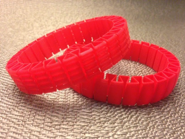
Today's knot print is a mosaic projection of 6_1: 


Thingiverse link: http://www.thingiverse.com/make:80243

Settings: Printed on a Replicator 2 with .3mm/low and normal support settings.

Technical notes, math flavor: This knot was designed and printed by JMU Student Taylor Meador. The images in her description below are from slides of a Knot Mosaic talk from Lew Ludwig of Denison College.

A mosaic projection of a knot is one that can be constructed as a mosaic using any of the 11 possible mosaic tiles:


We say that a mosaic projection is n-mosaic if it can be enclosed in an nxn square, and that the mosaic number of a knot is the minimum n such that the knot has an n-mosaic projection. The mosaic number for today's knot 6_1 is 5, and our conformation is taken from the figure below right:


Interestingly, as you can see in the figure, in order to realize a 5-mosaic projection of 6_1 we had to use an inefficient projection with seven crossings instead of six. In other words, in order to achieve a minimal mosaic number we had to use a projection with a non-minimal crossing number. 

Technical notes, OpenSCAD flavor: Taylor designed this model in OpenSCAD based on kitwallace's minimal stick code by constructing (x,y,z) corner coordinates near the crossings, based on the picture above right. She describes her process as follows:

The code is a list of coordinates interpreted directly from the 2D 6_1 mosaic. We added coordinates one at a time to make a path around the knot.  I reinterpreted the 5 x 5 mosaic board as an (x,y) coordinate plane in OpenSCAD, with each mosaic tile edge representing 4 units on the (x,y) plane.  I used the z-coordinate to allow the knot to pass over or under itself at the crossings; overcrossings simply remained at level z=1, and undercrossings were adjusted to z=0. For example, traveling across one mosaic tile from left to right while following an undercrossing would result in coordinates that move across, then down, then across, then up, then across: 

(x,y,1) --> (x+1,y,1) --> (x+1,y,0) --> (x+3,y,0) --> (x+3,y,1) --> (x+4,y,1).

The a and b parameters in the code allow us to scale the (x,y) plane separately from the z-axis, so that we can better adjust the clearance around and inside the crossings. 

Tuesday, May 27, 2014

Day 274 - Customizable Sock Bones

Sometimes I think I got into this 3D printing thing just so I would have the opportunity to say things like "customizable sock bones". Here they are:


These dogbone-like objects are for holding pairs of socks together, so you don't have to roll or tie up your socks. My sock drawer used to be an unholy mess of partnerless socks, but now it looks like this:


Let's be honest, though. If my sock drawer was really going to look like this then I wouldn't need any clips. After rummaging around it actually looks like this:


That's at least a thousand times better than its previous state, which I am not going to show you. The sock bones shown in these pictures work for standard men's socks, folded in half and then clipped in the middle. At the link below you'll also find a Customizer model that you can adjust to your size of socks.

Thingiverse link: http://www.thingiverse.com/thing:352805

Settings: Printed on a MakerBot Replicator 2 at .3mm/low. Printing six at a time takes about an hour, and it's a good way to use up scraps of filament you have lying around.

Technical notes, OpenSCAD flavor: This model is really simple; just a 2D shape made of circles and rectangles, extruded into 3D using linear_extrude.

// mathgrrl customizable sock bone

/////////////////////////////////////////////////////////////
// parameters ///////////////////////////////////////////////

// Length from one side of the sock to the other
length = 86; 

// Width/thickness of the folded sock
width = 13; 

// parameters that the user does not get to specify
$fn = 24*1;
radius = width*(8/13);
thickness = 2*1; 
height = 10*1; 

/////////////////////////////////////////////////////////////
// renders //////////////////////////////////////////////////

sockbone();

/////////////////////////////////////////////////////////////
// module for clip //////////////////////////////////////////

module sockbone(){
linear_extrude(height)
// 2D shape of bone holder
union(){
difference(){
// outer bone
union(){
translate([radius,0,0]) 
circle(radius);
translate([radius,-width/2,0]) 
square([length-2*radius,width]);
translate([length-radius,0,0]) 
circle(radius);
};
// take away inner bone
union(){
translate([radius,0,0]) 
circle(radius-thickness);
translate([radius,-(width-2*thickness)/2,0]) 
square([length-2*radius,width-2*thickness]);
translate([length-radius,0,0])
circle(radius-thickness);
}
// take away opening
translate([.25*length,0,0]) 
square(.5*length);
}
// rounded end caps
translate([.25*length,width/2-thickness/2,0])
circle(.7*thickness);
translate([.75*length,width/2-thickness/2,0])
circle(.7*thickness);
}
}

Monday, May 26, 2014

Day 273 - Lissajous conformation of 5_2

Today's knot is 5_2, the three-twist knot, in a Lissajous conformation. The cool thing about this model is that from each side, the knot looks like a wavy cosine function:


Thingiverse link: http://www.thingiverse.com/make:80103

Settings: MakerBot Replicator 2 with our custom knot-slicing profile.

Technical notes, math flavor: Lissajous knots are knots that can be parametrized by a triple of simple cosine functions, and are a subclass of Fourier knots. Although every knot can be expressed as a Fourier-(1,1,k) knot, not every knot is a Lissajous knot, that is, a Fourier-(1,1,1) knot. In this notation the (1,1,k) denotes how many cosine terms the parametrization has in each coordinate; for example, a Lissajous knot is (1,1,1) so has just one cosine function in each coordinate, but our trefoil from Day 151 is Fourier-(1,1,2) because its z-coordinate parametrization is a sum of two cosine functions. Today's 5_2 knot is the first knot in the standard table that can be expressed as a Lissajous knot, with just one cosine function in each coordinate.

Technical notes, OpenSCAD flavor: This knot was designed and printed by JMU student Patrick Moran. We used the slow but effective OpenSCAD "tubify" code from Day 151, and the parameters and phase shift values for 5_2 from the Wikipedia entry on Lissajous knots. However, this parametrization is built for knots with zero thickness, which of course would not print very well. With the thickness we needed for printing, the Wikipedia parametrization is self-intersecting:


In the code above, the factors of 180/3.14159 convert the phase shifts into degrees, since OpenSCAD does not use radians. The scaling factor of 30 in each coordinate allows a large enough knot parametrization to accommodate our radius of r=1.5. To fix the self-intersection of the original parametrization, Patrick re-scaled each coordinate individually as follows:

Sunday, May 25, 2014

Day 272 - Lattice conformation of 5_1

The cinquefoil knot 5_1 is one of two 5-crossing knots. The conformation we chose for this knot is a <LINK>lattice conformation<LINK>, which means that it follows only perpendicular directions in 3-space. In other words, this conformation is obtained by connecting integer-valued coordinates in space with straight lines.


Settings: Replicator 2 with our usual custom support settings for knots. 

Technical notes, math flavor: This knot was made by JMU student Kirill Korsak, who has this to say about lattice knots:

The lattice stick number for a knot is the minimal number of line segments required to construct that knot on a cubic lattice. While a stick configuration of a knot can consist of sticks of differing lengths, a lattice configuration is thought of as a collection of sticks of unit length. This means that if a knot on the cubic lattice has an edge that extends from, say, (0,0,0) to (0,0,3), then that length-three edge is considered to be three unit-length sticks lined up from end to end. It generally takes many more line segments to create a minimal lattice knot than to create a minimal stick knot. In fact it was shown in 1992 by Diao that the minimal number of sticks required to build a non-trivial knot on a cubic lattice is 24 (and that all such knots are trefoils), where we saw on Day 269 that the knot 4_1 can be made from just 7 variable-length non-lattice sticks. Today's 5_1 lattice knot is realized with 34 lattice points and therefore the lattice stick number of 5_1 is at most 34. However, it has not yet been proven that this is the minimal lattice knot configuration for 5_1.
 
Technical notes, OpenSCAD flavor: Kirill made this lattice knot with a modification of kitwallace's Mathematical Knots to OpenSCAD code that Greg used on Day 269, using data for the 5_1 lattice configuration obtained from the Minimal knots on cubic lattices page hosted by Andrew Rechnitzer of the University of British Columbia. Here is Kirill's resulting code:

Paths = [[[2,2,1],[1,2,1],[0,2,1],[0,3,1],[0,4,1],[1,4,1],[1,4,2],[1,4,3],[1,3,3],[1,2,3],[1,1,3],[1,1,2],[1,1,1],[1,1,0],[1,2,0],[1,3,0],[1,3,1],[1,3,2],[0,3,2],[0,4,2],[0,5,2],[1,5,2],[2,5,2],[2,4,2],[2,3,2],[2,2,2],[1,2,2],[0,2,2],[0,1,2],[0,0,2],[1,0,2],[2,0,2],[2,0,1],
[2,1,1]]];

// Sides of the tube
Sides = 20;
// Radius of tube
Radius = 0.39;
//Scale of knot
Scale=20;

module knot_path(path,r) {
for (i = [0 : 1 : len(path) - 1 ]) {
hull() {
translate(path[i]) sphere(r);
translate(path[(i + 1) % len(path)]) sphere(r);
}
}
};

module knot(paths,r) {
for (p = [0 : 1 : len(paths) - 1])
knot_path(paths[p],r);
};

$fn=Sides;
scale(Scale)
knot(Paths, Radius);

Saturday, May 24, 2014

Day 271 - Stretchy bracelets

It's Saturday and we are resting. Kids keep asking me for stretchy bracelets so today I made some from owens' Smooth and ridged stretchlets model on Thingiverse. They came out great! I love the ridgy one and in fact wore one of them around all day today until it finally broke because am a fidget queen who kept flipping it inside-out and pulling it off and on again. Also I'm a liar because I actually printed these and wore them around on Wednesday 5/28 but I'm pretending that I did it four days earlier for this blog post. 


Settings: Printed on a Replicator 2 with .3mm/low resolution and a custom profile to get no roof, no floor, 0% fill, and only one shell around the outside. I used a raft but I'm pretty sure that it wasn't really necessary.

Friday, May 23, 2014

Day 270 - Friday Fail: Measure-twice-print-once edition, with Poker chip racks

Today I wanted to design and print a rack for poker chips, and I wanted it to hold three stacks of 20 poker chips. If you sew, or knit, or build, or pretty much do anything, then you know you that should measure carefully, and preferably at least twice. I measured the chips. I remembered to measure the chips in a stack in case that was somehow mysteriously different than 20 times the height of one chip. I measured it a few times to be sure and because I always forget the first measurement number while I am re-measuring and then have to measure again. I remembered to add a millimeter to account for tolerance. Everything is great; measure, measure. Except that then I wrote this code:

radius = 20+1; // radius of actual poker chip plus fudge
height = 67+1; // height of actual stack of 20 chips plus fudge
thickness = 2; // desired thickness of plastic
shift = 2; // to make clean holes and/or holes with edges

difference(){
// outside cylinder
translate([0,0,radius]) 
rotate(90,[0,1,0]) 
cylinder(h=height,r=radius+thickness);
// take away chip cylinder
translate([thickness,0,radius+thickness]) 
rotate(90,[0,1,0]) 
cylinder(h=height-2*thickness,r=radius);
// take away top
translate([-shift,-.5*(height+2*shift),radius+thickness])
cube(height+2*thickness+2*shift);
// take away thumb cylinder
translate([-shift,0,radius+thickness]) 
rotate(90,[0,1,0]) 
cylinder(h=height+2*thickness+2*shift,r=radius-3*thickness);
}

And no amount of good measuring can overcome stupid code. Yet another rookie mistake: I used the 20-chips-plus-tolerance dimension for the outside and then took a smaller hole out of that to put the chips in. The resulting fail is on the left in the picture below; it only holds 18 chips. There is also an earlier bonus fail on the right from when I thought it would be a smart idea to print the rack upside-down without a raft.


Luckily, stupid fails are usually easy to fix; here's the corrected 20-chip version, along with a suitably Friday-Fail poker hand:


The design is now on Customizer and you can use it to make poker chip racks with variable numbers of rows and chips. If you use different denominations of chips then you could make one of these for each player. We currently play with just one denomination of chips so we use the three-row rack to hold all the chips for a short family poker evening and store the two-row rack to use when guests join our game:


Thingiverse link: http://www.thingiverse.com/thing:350083?save=success

Settings: MakerBot Replicator 2 with .3mm/low, printed with no supports but with a raft, on a glass build platform with blue painters tape.

Technical notes, OpenSCAD Customizer edition: Below is the full code that was submitted to the Thingiverse Customizer. Notice that the parameters at the top are meant to be entered by the user. The comments above these parameters are used by Customizer as descriptions in the user interface. The last group of parameters will not be visible to Customizer users. Any parameter that is computed will be ignored by Customizer. If you want a parameter to be invisible but it doesn't require any computation then just multiply it by 1 when it is defined. In the final code I also added a line to flatten the bottom of the rack so that it would have better contact with the build platform and its eventual resting place on the table.

// mathgrrl customizable poker chip rack

/////////////////////////////////////////////////////////////
// parameters ///////////////////////////////////////////////

// Diameter of one poker chip (in millimeters)
Chip_Diameter = 20; 

// Thickness of one poker chip (in millimeters)
Chip_Thickness = 3.35; 

// Number of chips you want in each row of the rack
Number_of_Chips = 20;

// Number of rows you want in the rack
Number_of_Rows = 3;

// Thickness of the rack itself
Rack_Thickness = 2; 

// Enter a tolerance (more if your chips are too tight, less if they are too loose)
Fudge = 1;

// Parameters invisible to the user
$fn = 96*1;
radius = Chip_Diameter/2 + Fudge;
height = Chip_Thickness*Number_of_Chips + Fudge;
thickness = Rack_Thickness*1;
rows = Number_of_Rows*1;
shift = 2*1; // to make clean holes and/or holes with edges

/////////////////////////////////////////////////////////////
// renders //////////////////////////////////////////////////

for (i = [1:1:rows]){
translate([0,(i-1)*(2*radius+thickness),0]) chipstack();
}

/////////////////////////////////////////////////////////////
// module for holding one stack of chips ////////////////////

module chipstack(){
// shift down to platform
translate([0,0,-.5])
difference(){
// outside cylinder
translate([0,0,radius+thickness]) 
rotate(90,[0,1,0]) 
cylinder(h=height+2*thickness,r=radius+thickness);
// take away chip cylinder
translate([thickness,0,radius+thickness]) 
rotate(90,[0,1,0]) 
cylinder(h=height,r=radius);
// take away thumb cylinder
translate([-shift,0,radius+thickness]) 
rotate(90,[0,1,0]) 
cylinder(h=height+2*thickness+2*shift,r=radius-1.5*thickness);
// take away top
translate([-shift,-.5*(height+2*shift),radius+thickness])
cube(height+2*thickness+2*shift);
// flatten bottom
translate([-shift,-5,-10+.5])
cube([height+2*thickness+2*shift,10,10]);
}
}

Thursday, May 22, 2014

Day 269 - Minimal stick conformation of 4_1

The figure-eight knot 4_1 is the only four-crossing knot, and it is usually drawn like the white knot on the left in the figure below. It is also the only knot whose stick number is 7, which means that the knot can be made out of 7 straight line segments, but no fewer. The tricky thing about studying stick numbers is figuring out how to prove the "but no fewer" part (see the Technical Notes below). Today's print is a 7-stick conformation of 4_1:


Thingiverse link: http://www.thingiverse.com/make:79819

Settings: Printed on a Replicator 2 with .2mm custom slicing profile.

Technical notes, math flavor: This knot was made by JMU student Greg Houchins, who put together the following nice survey of current known bounds on stick numbers:

The stick number of a knot is the minimal number of straight sticks joined together required to make a certain knot. More formally stated, it is the minimal number of edges of a polygon path that is equivalent to the given knot.  This knot invariant becomes very difficult to compute for large crossing knots and there is no given formula that works for all knots.  However, there have been some publications that have advanced the search for a universal formulation. Taek Jin published a paper in 1997 determining the stick number of torus knots, T(p,q) for relatively close p and q:

stick(T(p,q)) = 2q, if 2<= p < q <= 2p.

In 1991, Seita Negami was able to put a bound on the stick number, which he called broken line number, of knots proving that for a knot K with crossing number c(K) we have:

(1/2)(5+sqrt(25+8(c(k)-2))) <= stick(K) <= 2 c(K).

Jorge Calvo was able to raise the lower bound in his 2001 paper to

(1/2)(7+sqrt(8c(K)+1)) <= stick(K).

The upper bound was later improved further by Seungsang Oh and Youngsik Huh to

stick(K) <= (3/2)(c(K)+1). 

Technical notes, OpenSCAD flavor: To make the stick model of 4_1, Greg used kitwallace's amazing Mathematical Knots to OpenSCAD website, which generates OpenSCAD knot code based on data it pulls from The Knot Server. Here is Greg's description of the process:

To create a 3D model of a stick conformation, all we need to do is put spheres at the points where the sticks meet and then connect these spheres. Fortunately, not only are the coordinates of these sphere points available, but an OpenSCAD file is available implementing this idea at kitwalace.co.uk/3d/knot.xq. On this site, you enter the number that the knot is listed as in the Knot Atlas.  The figure-eight knot 4_1 is the third knot in the Knot Atlas so we enter 3 as the "Knot Type". Then under the dropdown menu for render type, select stick, then press download, as shown in this screenshot:

When the resulting file is opened in OpenSCAD, the knot will be very thin and not suitable for 3D printing. To thicken the knot, you can adjust the radius parameter. However, the thicker knot may overlap itself. To change this we can manipulate the end points in order to open the knot up so that the sides no longer overlap. The code used for the model is as follows.

Knot_name = "Minimal stick candidate for 4.1";
Knot_type = "3";
Paths = [
[
[1.417090,-2.384662,-3.062703],//(+,-,-)
[-1.114094,3.107347,0.801322],//(-,+,+)
[-2.493145,-3.558361,2.356218],//(-,-,+)
[-0.108153,2.428202,-2.660958],//(0,+,-)
[3.607935,-4.376481,1.075724],//(+,-,+)
[-3.552488,-0.384435,-0.962569],//(-,-,-)
[3.922855,2.868389,1.952966]//(+,+,+)
]
];

// Sides of the tube
Sides = 20;
// Radius of tube
Radius = 0.38;
//Scale of knot
Scale=20;

Colors = [[1,0,0],[0,1,0],[0,0,1],[1,1,0],[1,0,1],[0,1,1]];
module knot_path(path,r) {
   for (i = [0 : 1 : len(path) - 1 ]) {
      hull() {
         translate(path[i]) sphere(r);
         translate(path[(i + 1) % len(path)]) sphere(r);
      }
   }
};

module knot(paths,r) {
   for (p = [0 : 1 : len(paths) - 1])
      color(Colors[p])
         knot_path(paths[p],r);
};

$fn=Sides;
scale(Scale)
knot(Paths, Radius);

Once you are happy with the knot conformation, press F_6 in OpenSCAD to render the model in full quality so it can be exported.

Wednesday, May 21, 2014

Day 268 - Tritangentless conformation of 3_1

The trefoil knot 3_1 is the only three-crossing knot, which means that every other knot that can be drawn as a projection in the plane with three crossings (and no fewer) must be topologically equivalent to a trefoil knot. In my opinion the coolest thing about the trefoil is that it has a tritangentless conformation. In such a conformation, there are no planes that are tangent to three points on the knot simultaneously. For those planes on the exterior of the knot this means that if you put the knot on a table, the knot will only touch the table in at most two places. On the left in the picture below is shown a standard trefoil conformation, and on the right is the same trefoil knot but in a tritangentless conformation (the same "rocking knot" model that we printed on Day 110 and Day 151):


Thingiverse link: http://www.thingiverse.com/make:78751

Settings: Replicator 2 with custom knot slicing/support profile.

Technical notes, see previous posts: See Day 110 for the parametric equations that describe this tritangentless trefoil conformation, a link to the paper those equations were found in, and details about the custom slicing profile. See Day 151 for the OpenSCAD code that will generate this knot without the "seam" that appears if you try to model it in Mathematica. For other interesting conformations of the trefoil see the Trefoil Menagerie on Thingiverse.

Tuesday, May 20, 2014

Day 267 - Crazy conformation of 0_1

Today we'll start going through the knot conformations in the series we introduced yesterday. Before we begin, let's go over some of the basic notation and ideas of knot theory.

Knots are embeddings of S^1 into S^3, if you're a mathematician. If you're a normal person then you can think of knots as pieces of string that are tied into some knotted shape with their ends then fused together. Knots are named according to their position in the standard Rolfsen table, with names like 3_1, 7_2, and 8_19. The first number in the name represents the minimum possible number of crossings for a projection of the knot, and the second number is just its position in the table among knots with the given minimum crossing number. For example, 8_19 is the nineteenth knot in the list of 8-crossing knots in the Rolfsen table.

The unknot is the simplest type of knot; think of it as a piece of string with its ends joined together, with no knotting along the way. In other words, the unknot is just a circle. It requires no crossings, and it is the only knot that can have a 0-crossing projection, so its name is 0_1 (the first, in fact the only, 0-crossing knot).

When we say "the" unknot we actually mean a whole collection of things: anything that can be continuously deformed into a simple circle. So the unknot could sit in space as a perfect circle, or a much larger circle, or an oval, or curving around in any way we like - as long as it can continuously morph into a circle shape without breaking or tearing. One thing we often try to figure out in knot theory is whether or not a given knot is in fact the unknot. Sometimes this is easy to see, and sometimes it isn't. For example, the first knot conformation pair in our series is the standard circle form of the unknot together with a much more interesting, non-trivial-looking conformation. If the green knot on the right were made of a stretchy rubber band, we would be able to move that rubber band around in space without breaking it until it was in the shape of a circle. Can you see how? If you like questions like this then you might enjoy the mathematical field of topology, where two objects are considered equivalent if they can be morphed into each other without tearing or gluing (for example the famous donut = coffee cup example).


Thingiverse link: http://www.thingiverse.com/make:78732

Settings: MakerBot Replicator 2 on .3mm/low with the support-reducing slicing profile from Day 110.

Technical notes, KnotPlot flavor: Both of these knots were made by JMU student Kirill Korsak using the excellent program KnotPlot. KnotPlot is free, but to export 3D-printable files from it you will have to pay the registration fee. Here's how Kirill describes making these knots with KnotPlot:
  1. In the KnotPlot control panel click on the tab that says "DemoA". You should see the menus as in the picture below.
  2. Click on the button that says “Nasty”, and a knot should appear in the KnotPlot display window. You can pan the knot around with your mouse; you’ll notice that the knot is essentially flat in 2 dimensions, which will not work well for 3D printing. 
  3. We need to relax the knot to give it more dimensionality. To do this, click on the tab called “Dyna” in the KnotPlot command window. Observe that the parameters “elec” and “mech” are turned on by default as the little box next to them is highlighted orange.
  4. To see what these parameters do you can click the “go” button after which the button will turn green and the knot will begin to relax. To select a particular conformation mid-relaxation you will have to quickly click and then immediately unlick the "go" button to freeze the knot.
  5. As a bonus you can turn off both the “elec” and “mech” parameters and just turn on the drag parameter. Now when you hit go, the knot will not relax by itself; instead you can drag the knot manually by clicking on it with the mouse! This is extremely useful, as you can get the knot to look exactly how you want with just some manual labor.
  6. To export your beautiful creation, you will have to use the KnotPlot Command Window. This is the command line interface window. Type in “objout nameofknot” without the quotes and the knot in your current KnotPlot display window will be exported to an OBJ file as soon as you hit enter.
  7. If you need an STL file for printing, then you can convert your OBJ to STL by using the online tool located at http://www.greentoken.de/onlineconv/.

Monday, May 19, 2014

Day 266 - 3D Printed Conformations of Knots

The final project for this semester's MATH 297 - Knot Theory Research and 3D Printing course was to research and print a set of interesting knot conformations for the first fifteen knots in the Rolfsen knot table. The students recently presented their work at the Spring MD/DC/VA MAA meeting, and thanks to the Institute for Visual Studies these knots will be on permanent display at the entrance of Roop Hall, home of the JMU Department of Mathematics and Statistics.

Over the next couple of weeks we will have a series of guest posts in which we go through the knot conformation models created by the five James Madison University students in the course: Jonathan Gerhard, Gregory Houchins, Kirill Korsak, Taylor Meador, and Patrick Moran. Here is the abstract for the project:
3D Printed Conformations of Knots through 7 Crossings 
Knots are embeddings of circles in 3-dimensional space, but they are typically studied in terms of their projections into 2-dimensional space. We can use 3D printing to study knots in a more 3-dimensional way. In this series we present 3D printed conformations of the fifteen knots through seven crossings, including stick, Lissajous, lattice, torus, petal, and pretzel conformations.  Constructing a 3D model that is actually printable can challenging; to 3D print the knot conformations through seven crossings, we used a combination of Mathematica, Blender, Tinkercad, Knotplot, SeifertView, and OpenSCAD. 
And here is the full set of printed models, where each of the 15 knots through seven crossings is printed in both a standard conformation (in white) and one other interesting conformation (in color, directly below its white counterpart):


Settings: All of these knots were printed on a MakerBot Replicator 2, with various choices of settings depending on the conformation design.

Sunday, May 18, 2014

Day 265 - Cairo and prismatic pentagons

Today we fix our fail from Friday (Day 263), and print Cairo pentagons and prismatic pentagons from data kindly provided by Frank Morgan's student Maggie Miller at Williams College.

I have a special place in my heart for tessellating pentagons because of the late, legendary Paul Sally at the University of Chicago. While I was an undergraduate at Chicago I had very little money and needed all the extra work I could get. Sally was kind enough to hire me for small jobs whenever he could, and one of the jobs he gave me was to measure, cut, and arrange paper models of various types of tessellating pentagons. I was terrible at this job; the smallest errors in angle or cut would magnify as they propagated through the tiling. One other time Sally hired me to clean every individual leaf of a large tree he kept in his office with a tiny spray bottle. I totally rocked that job.

So in honor of Paul Sally, here is a pentagonal tiling where all of the 3D-printed pieces are perfect and everything actually works:


Those were the "Cairo" pentagons. Here's a tiling with the "prismatic" pentagons:


And here is one that uses a combination of Cairo and prismatic pentagons:


Thingiverse link: http://www.thingiverse.com/thing:338803

Settings: Printed on a MakerBot Replicator 2 on .3mm/low resolution.

Technical notes, math flavor: These three pictures are copies of the first tilings shown in the beautiful paper Isoparametric pentagonal tilings that Frank Morgan and his students published in the Notices of the AMS in 2012. In that paper the picture of the third tiling above looks a lot different because different colors are used for adjacent pentagons:


The colors in that figure show off some beautiful structures in the tiling, but I think I prefer the simpler homogenous coloring that arises from the 3D-printed tiles, where it is easy to see at a glance which of the tiles are Cairo and which are prismatic. In their Notices paper, Morgan and students illustrate many other types of Cairo-prismatic tilings, many of which are nonperiodic, for example the following famous nonperiodic Cairo-prismatic tiling discovered by amateur mathematician Marjorie Rice:

Saturday, May 17, 2014

Day 264: Sir Not-Appearing-in-This-Film

To finish the furniture series we have one final print: some of the pieces that we couldn't fit into our apartment and that will be traveling to North Carolina to live with my sister Alina. And this is just the furniture we thought might fit - some pieces we didn't even bother to print because we knew there was no chance. Perhaps this is a good time to remind ourselves of some of the things we are really looking forward to in the city: The Brooklyn Strategist, Dassara, and the F Train!


Thingiverse link: http://www.thingiverse.com/thing:332507

Friday, May 16, 2014

Day 263: Friday Fail: Off-by-one edition

Being off by one is probably the simplest, most common coding mistake you can make, but it got me this week while I was trying to make tessellating Cairo pentagon tiles for Frank Morgan and his students at Williams College. These Cairo tiles are supposed to have a mirror symmetry as shown in the drawing below, but the ones I printed didn't have this symmetry, so I knew something was wrong.


It took me a while to figure it out, but the culprit was a for loop in OpenSCAD that I had started at 1 instead of 0. By "a while" I mean I didn't figure it out until the next day! It's obvious now, but maybe knowing what kind of error this can cause in a 3D model will help someone else identify this mistake sooner than I did, so let me explain. The coordinates I was using for the pentagon were as follows:

/////////////////////////////////////////////////////////////
// point data ///////////////////////////////////////////////

points_cairo = [
[-1,0],[1,0],[2.3660,2.3660],[-2.3660,2.3660],[0,3.7321]
];

My simple pentagon module just forms the convex hull around five spheres at these points, and five spheres translated a bit up from these five points, to make a rounded pentagon tile:

/////////////////////////////////////////////////////////////
// render ///////////////////////////////////////////////////

pentagon(points_cairo,radius=.5,scale=5,height=2); 

/////////////////////////////////////////////////////////////
// pentagon module //////////////////////////////////////////

module pentagon(points,radius,scale) {
hull(){
for (i = [0:4]){
// the five points of the pentagon
translate(scale*points[i]) sphere(radius);
// repeat the pentagon points at a higher level
translate([0,0,height]) translate(scale*points[i]) sphere(radius);
}
}
}

The code above is the correct code for the Cairo pentagon; my original code erroneously ran the loop from 1 to 5 instead of from 0 to 4. OpenSCAD thought of the Cairo data set as indexed from i=0 to i=4, so my original loop from 1 to 5 was interpreted by OpenSCAD as taking i=1 through i=4 and then some mystery i=5 datapoint that was not defined. You can see in the picture of the printed tiles that OpenSCAD decided to make this i=5 datapoint the origin (0,0) instead of returning an error. 

This is one of the things I find most difficult about debugging OpenSCAD code: if I have an error in my code, sometimes OpenSCAD finds a way to compile anyway, either ignoring my code or substituting something it can handle, as it did here. 

Stay tuned for the correct print of these tessellating pentagons later this weekend...

Thursday, May 15, 2014

Day 262 - Customizable Furniture Minis

Today our Customizable Furniture Minis set is finally done and posted to Thingiverse! I guess it's time to actually start packing now...


Settings: All models printed on a Replicator 2 with .3mm/low resolution, with no support and no raft. 

Technical notes: For discussions of the OpenSCAD code used to make these models, see the MakerHome posts from the last couple of weeks. In addition you can see the version of the OpenSCAD code that is built to work with the Thingiverse Customizer by viewing the code from within the Customizer. For learn how to change your own OpenSCAD code into something for the Customizer, see MakerBot's helpful Best Practices and Developer Documentation pages. It's an easy process that mostly involves passing commands to the Customizer through comments in your OpenSCAD code.

Wednesday, May 14, 2014

Day 261 - Clearance stars

Sometimes with scaled floor plans it is difficult to tell if your setup is crowded or not. To test out the openness of our layout we printed two "clearance stars" to represent an individual's personal space as they moved through the apartment. According to homeplanner.com, for limited access spaces - like passageways behind furniture - a space of 24 inches should be allowed. For high-traffic spaces they suggest a space of 36 inches. But hey, it's a New York City apartment, not a spacious country home, so we took those measurements down a little bit after measuring the minimum comfortable clearances in our current home. We ended up settling on 22 inches clearance for limited access spaces, and 30 inches for high-traffic areas. The star models represent 1:50 scale of six feet tall so you can imagine them sort of as people with extra elbow room poking out all around. Here they are proving that we will be able to fit in the apartment along with all the furniture:


Thingiverse link: http://www.thingiverse.com/make:78720

Settings: MakerBot Replicator 2 at .3mm/low resolution.

Technical notes, OpenSCAD flavor: This model is just a tall twelve-pointed star column with a smaller copy of itself hollowed out of the middle. The star is a union of three (4-pointed, of course) squares, each rotated 120 degrees from the last, with code borrowed from Catarina Mota's shape library:

/////////////////////////////////////////////////////////////
// module for clearance star ////////////////////////////////

module 12ptstar(width,height) {
starNum = 3;
starAngle = 360/starNum;
// place StarNum cubes rotated evenly
for (s = [1:starNum]) {
rotate([0, 0, s*starAngle]) cube([width/sqrt(2),width/sqrt(2),height], true);
  }
}

module clearance_star(width,height) {
scale(s)
difference(){
12ptstar(width,height);
12ptstar(width-6,height+2);
}
}

Here are the lines of code for rendering the two stars:

// limited access clearance star 
//clearance_star(width=22,height=72);

// high-traffic access clearance star 
//clearance_star(width=30,height=72);

Tuesday, May 13, 2014

Day 260 - Bed frame and floor plan

Today's print is very simple: just a snap-around bed frame to model the wooden frame around our king-size bed. As you can see in the picture, we've chosen the smallest of the bedrooms to be our "master" bedroom, and the bed will take up pretty much all of the room. The closet at the bottom of the picture is part of this bedroom, but the other closet is actually a piece taken out of this small room to make a closet for the bedroom to the right. We made the actual larger "master bedroom" into the office (Day 255), with the thought that we'd rather have extra room while awake than asleep.

The picture below also shows off the nice floor plan that P made in Illustrator from the measurements that the real estate broker and building super were kind enough to make for us. The floor plan is made 1:50 scale to match the printed furniture. My Mother's Day gift this year was for everyone else in the house to pretend to be as excited as I am about spending time obsessively modeling our new apartment, so we're almost done now with all the furniture...


Thingiverse link: http://www.thingiverse.com/thing:332507

Settings: MakerBot Replicator 2 on .3mm/low, as usual.

Technical notes, easiest-OpenSCAD-code-ever flavor: The design is just a sharp cuboid (see Day 248) with a smaller one taken out so that the bed can fit inside.

/////////////////////////////////////////////////////////////
// module for making bed frames /////////////////////////////

module bedframe(depth,length,height){
scale(s)
difference(){
// total outer size
cuboid(depth,length,height,sharp);
// take out inside
translate([2,2,-1]) cuboid(depth-4,length-4,height+2,sharp);
}
}

Monday, May 12, 2014

Day 259 - Workshop desk and kid-size bureau

This will be our last week of printing tiny furniture; after a few more days we'll have a full set and will post everything to the Thingiverse Customizer so that all the summer movers out there can print-and-plan their new spaces. Today we printed C's room, including a modular IKIEA Linnmon table-desk with corner piece and a small chest of possibly-discontinued IKEA Trofast drawers.


Thingiverse link: http://www.thingiverse.com/make:78721

Settings: Replicator 2 on .3mm/low, with the bureau printed on its back and the desks printed upside-down to enable printing without supports or raft.

Technical notes, OpenSCAD flavor: The desk module builds a simple inverted-C shape and the cornerdesk module is just with the same code with a cylinder removed from one corner.

/////////////////////////////////////////////////////////////
// module for making desks //////////////////////////////////

module desk(depth,length,height){
scale(s)
union(){
// top of desk
translate([0,0,height*.8]) cuboid(depth,length,height*.2,sharp);
// left side
cuboid(depth,length*.15,height,sharp);
// right side
translate([0,length*.85,0]) cuboid(depth,length*.15,height,sharp);
}
}

/////////////////////////////////////////////////////////////
// module for making corner desks ///////////////////////////

module cornerdesk(depth,length,height){
scale(s)
difference(){
// regular desk
union(){
// top of desk
translate([0,0,height*.8]) cuboid(depth,length,height*.2,sharp);
// left side
cuboid(depth,length*.15,height,sharp);
// right side
translate([0,length*.85,0]) cuboid(depth,length*.15,height,sharp);
}
// take out a corner circle
translate([0,0,-1]) cylinder(r=depth/2,h=height+2);
}
}

The bureau module is a modified version of the bookcase module from Day 232, with drawers as shifted two-up shelves that stick out instead of make holes. It's adorable and I wish we had more than one chest of drawers to print!

/////////////////////////////////////////////////////////////
// module for bureaus ///////////////////////////////////////

module bureau(depth,length,height,drawers){
scale(s)
union(){
// body of the bureau
cuboid(length,height,depth,sharp);
// put in some drawers
for (i = [1:1:drawers]){
translate([.075*length,i*(height-.1*height)/drawers-.15*height,0]) 
cuboid(.4*length,.15*height,depth*1.1,sharp);
translate([.525*length,i*(height-.1*height)/drawers-.15*height,0]) 
cuboid(.4*length,.15*height,depth*1.1,sharp);
}
}
}